Nanofiber mats, method of manufacturing the nanofiber mats, and applications to cell culture and nanofibrous membrane for guided bone regeneration

a nanofiber and mat technology, applied in the field of nanofiber mats, can solve the problems of increased cost, limited application range, and difficult handling of the material, and achieve the effects of high flexibility and elasticity for the ease of handling, sufficient structural reinforcement, and improved rigidity

Active Publication Date: 2016-09-01
STONE CORP
View PDF0 Cites 17 Cited by
  • Summary
  • Abstract
  • Description
  • Claims
  • Application Information

AI Technical Summary

Benefits of technology

[0024]According to such a nanofiber mat, a manufacturing method thereof, and applications thereof as a mat for cell culturing or as a barrier membrane for GBR, the inclusion of a nanofiber layer enables an attainment of biocompatibility, shielding, long-term drug-releasing, and an improvement of rigidity by a reinforcement pattern that mechanically reinforces the nanofiber layer. A nanofiber mat that exhibits high flexibility and elasticity for the ease of handling and is sufficiently structurally reinforced while being not limited to a particular shape can be produced. Also, by having a wide range of usability as a mat including the ease of handling, it can be used in various fields without being limited to conventional and restrictive ways of use.
[0025]Particularly, it may be easily use...

Problems solved by technology

However, nanofiber mats are highly flexible, and thus handling thereof is not easy and there is much limitation to maintaining an evenly spread shape inside a dish.
Therefore, they are initially fabricated into a form of an attachment to a cell culture dish or prepared with a very large thickness, and thus it is difficult to use them in various ways during an experiment, and they have various problems such as an increased cost and limited range of application.
Inorganic barrier membranes have advantages such as high rigidity and high structural stability, but they are highly incompatible with a human tissue.
However, both inorganic barrier membranes and no...

Method used


Image

  • Nanofiber mats, method of manufacturing the nanofiber mats, and applications to cell culture and nanofibrous membrane for guided bone regeneration
  • Nanofiber mats, method of manufacturing the nanofiber mats, and applications to cell culture and nanofibrous membrane for guided bone regeneration
  • Nanofiber mats, method of manufacturing the nanofiber mats, and applications to cell culture and nanofibrous membrane for guided bone regeneration

Examples


example 1

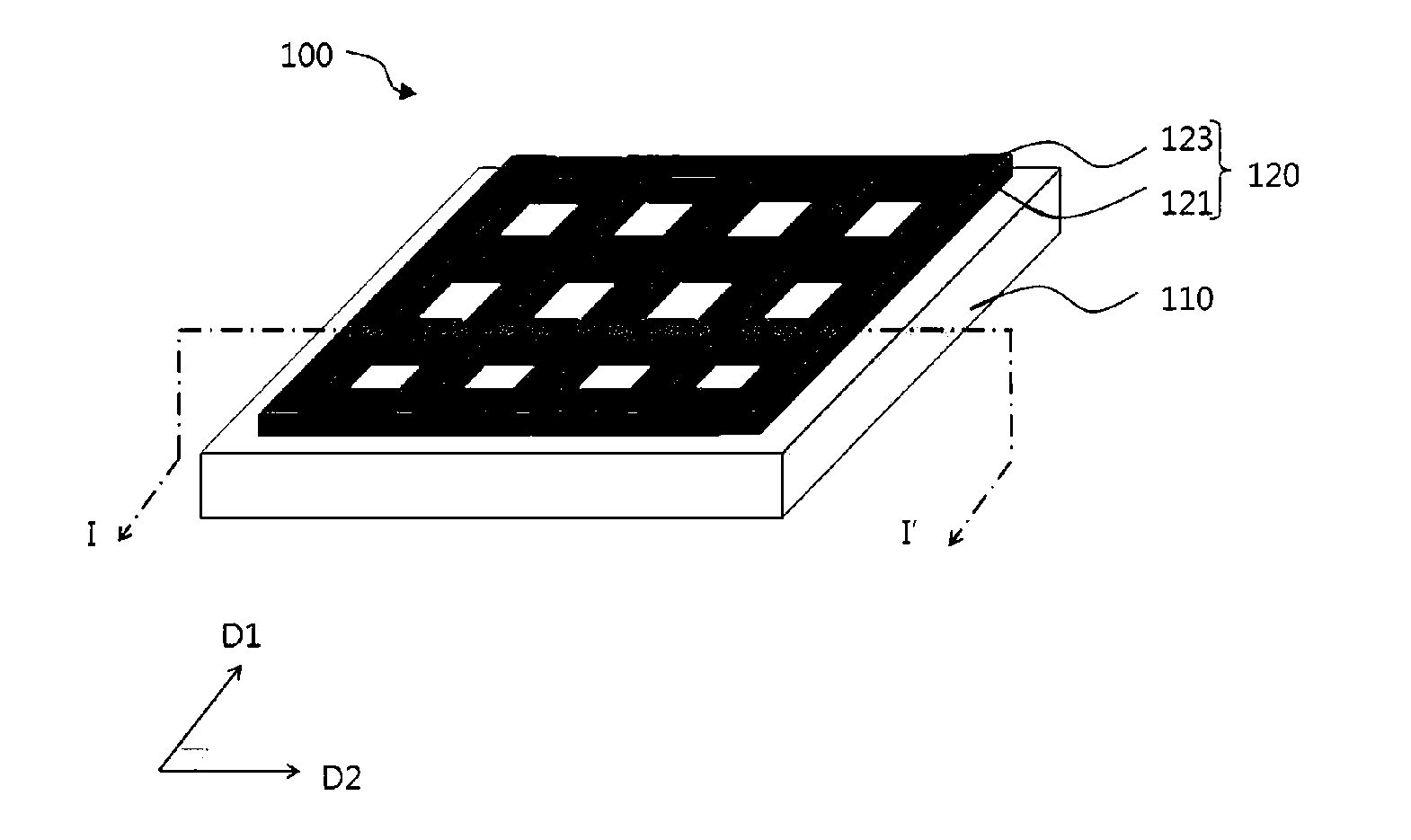
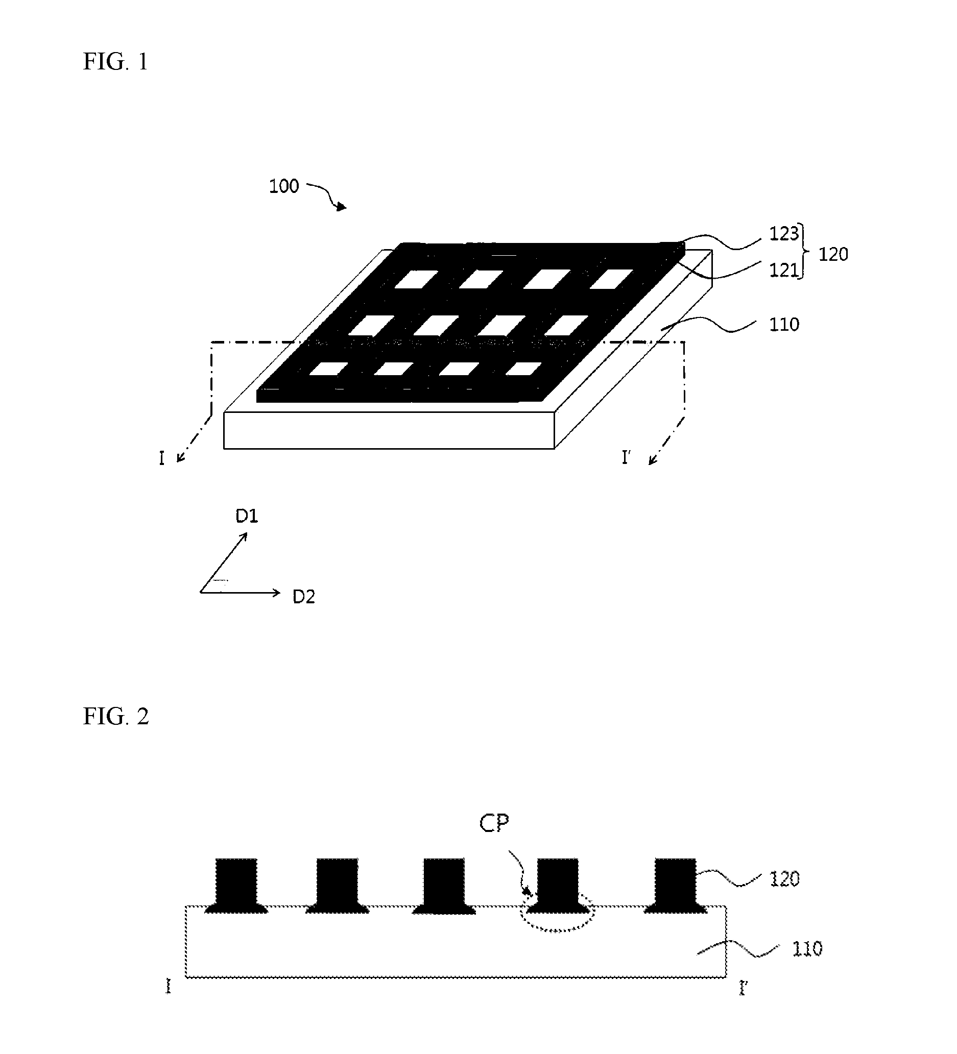
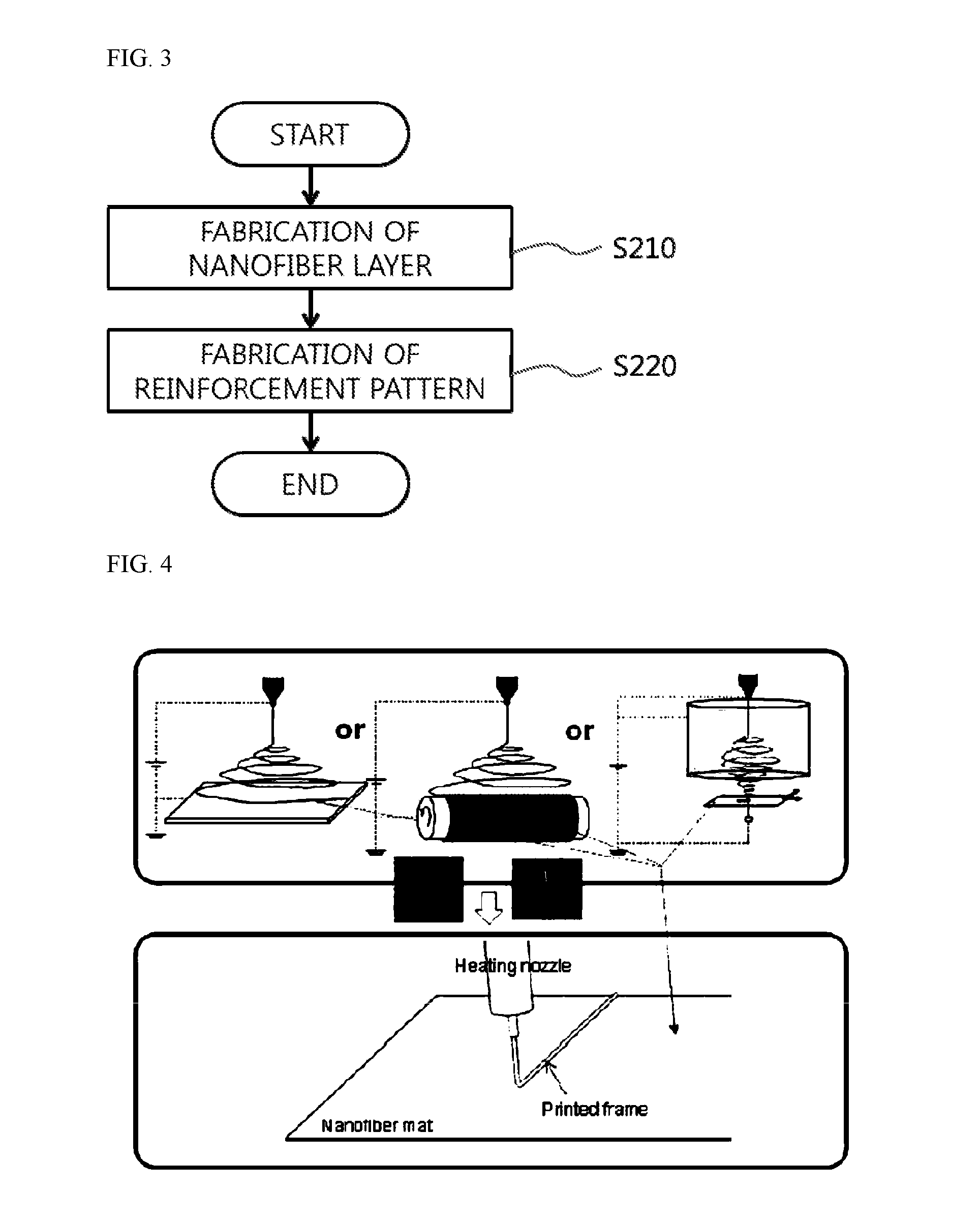
[0118]A 9 wt % solution prepared by dissolving PCL with a number average molecular weight (Mn) of about 80,000 in chloroform was electrospun to a 150-μm thick glass collector under process conditions including a spinning distance (nozzle-to-collector distance) of 70 mm, voltage of 20 kV, and a flow rate of 0.1 ml / h. On the produced nanofibers, a reinforcement pattern was printed by an FDM process and using a PCL-melt under process conditions including a temperature of 100° C., pressure of 600 kPa, scanning speed of 100 mm / min, nozzle diameter of 150 μm, and a jetting distance of 150 μm. A thickness of the obtained nanofiber mat was 100 μm, and a diameter of the reinforcement was 150 μm.

example 2

[0119]A 9 wt % solution prepared by dissolving PCL with a Mn of about 80,000 in chloroform was electrospun to a drum-shaped collection screen, which rotates at 3000 rpm, under process conditions including a spinning distance of 70 mm, voltage of 20 kV, and a flow rate of 0.1 ml / h. After spinning, the cylindrical nanofiber was cut flat. On the produced nanofibers, a reinforcement pattern was printed by an FDM process and using a PCL-melt under process conditions including a temperature of 100° C., pressure of 600 kPa, scanning speed of 100 mm / min, nozzle diameter of 150 μm, and a jetting distance of 150 μm. A thickness of the obtained nanofiber mat was 120 μm, and a diameter of the reinforcement was 150 μm.

example 3

[0120]A 9 wt % solution was prepared by dissolving 500 mg of PCL with a Mn of about 80,000 in chloroform. 10 μg of BMP-2 and 50 mg of PEG were dissolved in 2 ml of DCM, added to the PCL solution previously prepared, and stirred thoroughly for 30 minutes. Then, it was electrospun to a 150-μm thick glass collector under process conditions including a spinning distance of 70 mm, voltage of 20 kV, and a flow rate of 0.1 ml / h. On the produced nanofibers, a reinforcement pattern was printed by an FDM process and using a PCL-melt under process conditions including a temperature of 100 ° C., pressure of 600 kPa, scanning speed of 100 mm / min, nozzle diameter of 150 μm, and a jetting distance of 150 μm. A thickness of the obtained nanofiber mat was 100 μm, and a diameter of the reinforcement was 150 μm.


PUM

PropertyMeasurementUnit
Flexibilityaaaaaaaaaa
Shapeaaaaaaaaaa
Stiffnessaaaaaaaaaa

Abstract

Disclosed are a nanofiber mat, a manufacturing method thereof, and applications thereof as a mat for cell culturing or as a barrier membrane for guided bone regeneration (GBR). The nanofiber layer includes a nanofiber layer and a reinforcement pattern that is disposed on the nanofiber layer and adhesively connected with the nanofiber layer. The nanofiber layer and the reinforcement pattern are combined with each other by at least one of the melting-solidification of at least a part of the nanofiber layer together with the reinforcement pattern, the dissolution-solidification of the same, and the penetration of a part of the reinforcement pattern into the nanofiber layer, followed by solidification.

Description

TECHNICAL FIELD[0001]The present invention relates to a nanofiber mat, a manufacturing method thereof, and applications thereof as a mat for cell culturing or as a barrier membrane for guided bone regeneration (GBR), and, more particularly, to a nanofiber mat with an ease of handling, a manufacturing method thereof, and applications thereof as a mat for cell culturing or as a barrier membrane for GBR.BACKGROUND ART[0002]In recent years, much attention has been paid to nanofibers, and they have been subjects of great interest in an aspect pertaining to cell culturing. In particular, fibers produced by electrospinning are fibers with a very small diameter, and they are advantageous in that they have a very large surface area per unit volume, are flexible, highly porous, and a large number of fibers are present per unit area, thus being capable of blending with other material(s) and exhibiting large distribution of an external stress. In a biomedical field, nanofiber aggregates (e.g. n...

Claims


Application Information

Patent Timeline
IPC IPC(8): A61L31/12C12N5/077C12N5/00A61L31/16A61L31/14
CPCA61L31/125A61L31/16A61L31/146C12N5/0068C12N2533/30A61L2400/12A61L2430/02C12N2535/10C12N2537/00C12N5/0654A61L27/54A61L27/56C12M25/14A61L27/18A61L27/3821C08L67/04
Inventor JEONG, YOUNG HUNKWAK, JONG-YOUNGKIM, JEONG HWAKIM, CHANG GUN
Owner STONE CORP
Why Eureka
Try Eureka