Method and Device for Estimation of Chromatic Dispersion in Optical Coherent Communication

a chromatic dispersion and optical coherent communication technology, applied in electromagnetic transmission, electrical equipment, transmission, etc., can solve the problems of fir butterfly adaptive equalizer not working properly, conventional clock recovery usually can only tolerate small dispersion, and the complexity of clock recovery modules is reduced. , to achieve the effect of accurately estimating the dispersion value, and reducing the complexity of the clock recovery modul

Active Publication Date: 2016-09-15
SANECHIPS TECH CO LTD
View PDF9 Cites 8 Cited by
  • Summary
  • Abstract
  • Description
  • Claims
  • Application Information

AI Technical Summary

Benefits of technology

[0011]To solve the technical problem, the embodiment of the present invention is to provide a dispersion estimation method and device in coherent optical communication to improve the dispersion measurement accuracy and efficiency.
[0073]The abovementioned technical solution can directly calculate the dispersion without searching, thus, when the system starts, the value of the link dispersion can be quickly estimated. When the system is running, it may also continue to estimate the link dispersion value, track its change, and ensure the dispersion compensation module to precisely compensate the dispersion. It can achieve precise dispersion compensation, and can reduce the complexity of the clock recovery module thereafter, and the like. To sum up, compared with the related art, the abovementioned technical solution can very accurately estimate the dispersion value, and the estimation speed is fast.

Problems solved by technology

When the bit rate per wavelength increases, the chromatic dispersion, polarization mode dispersion, and waveform distortions of various non-linear effects in the transmission path result in serious degradation in the quality of the information.
When the sampling position change range is too large, or the sampling frequency offset exists, the sampling phase change range exceeds the adjustment range of the FIR butterfly adaptive equalizer, it will cause the FIR butterfly adaptive equalizer to not work properly.
The clock recovery phase detector needs to tolerate a certain signal distortion, while the conventional clock recovery usually can only tolerate small dispersion.
In order to not increase the complexity of the clock recovery module, while currently there is a lack of clock recovery method that tolerances large residual dispersion value, it requires an accurate dispersion compensation.
When the system starts up, the search process is slow and the accuracy is low.
Moreover, the optical fiber link is affected by the environmental temperature change, and the link dispersion value also changes slowly.
In addition, in the working process, with the search based dispersion estimation method in the related art, it is difficult to judge a slow change of the dispersion value in the operation.

Method used


Image

  • Method and Device for Estimation of Chromatic Dispersion in Optical Coherent Communication
  • Method and Device for Estimation of Chromatic Dispersion in Optical Coherent Communication
  • Method and Device for Estimation of Chromatic Dispersion in Optical Coherent Communication

Examples


first embodiment

The First Embodiment

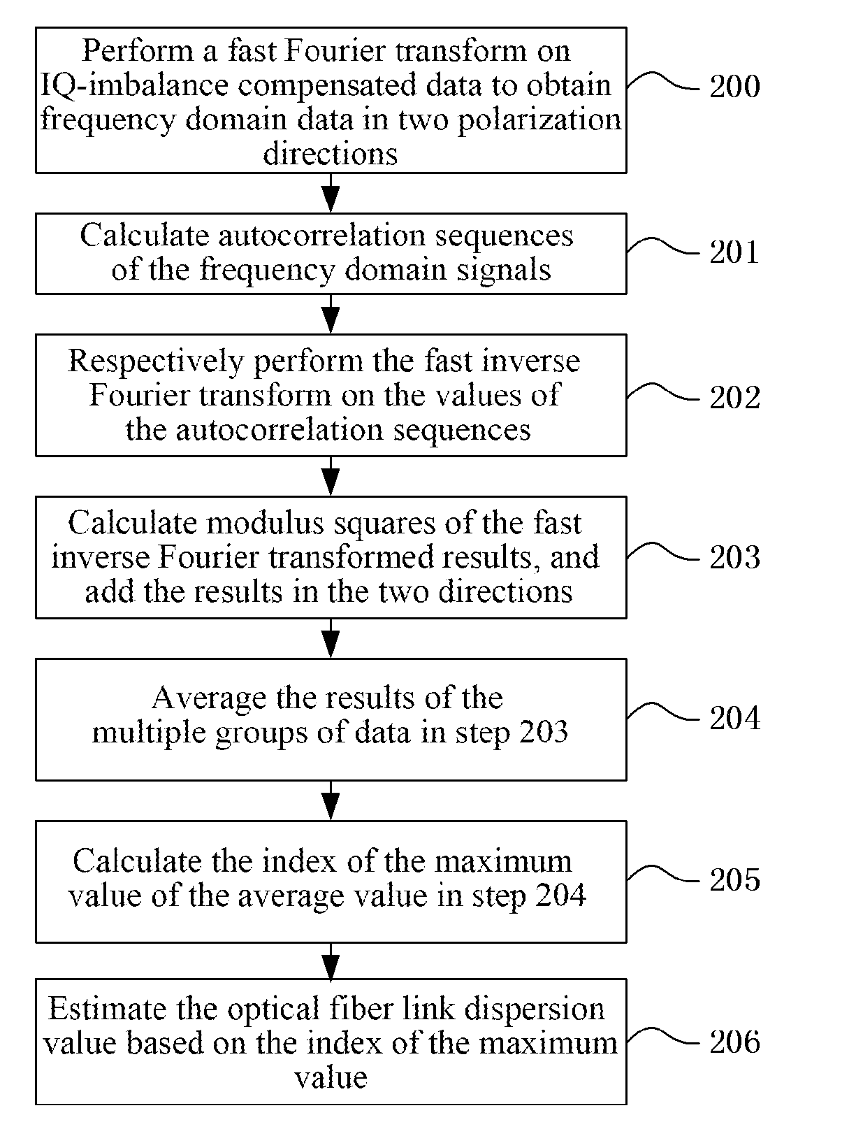
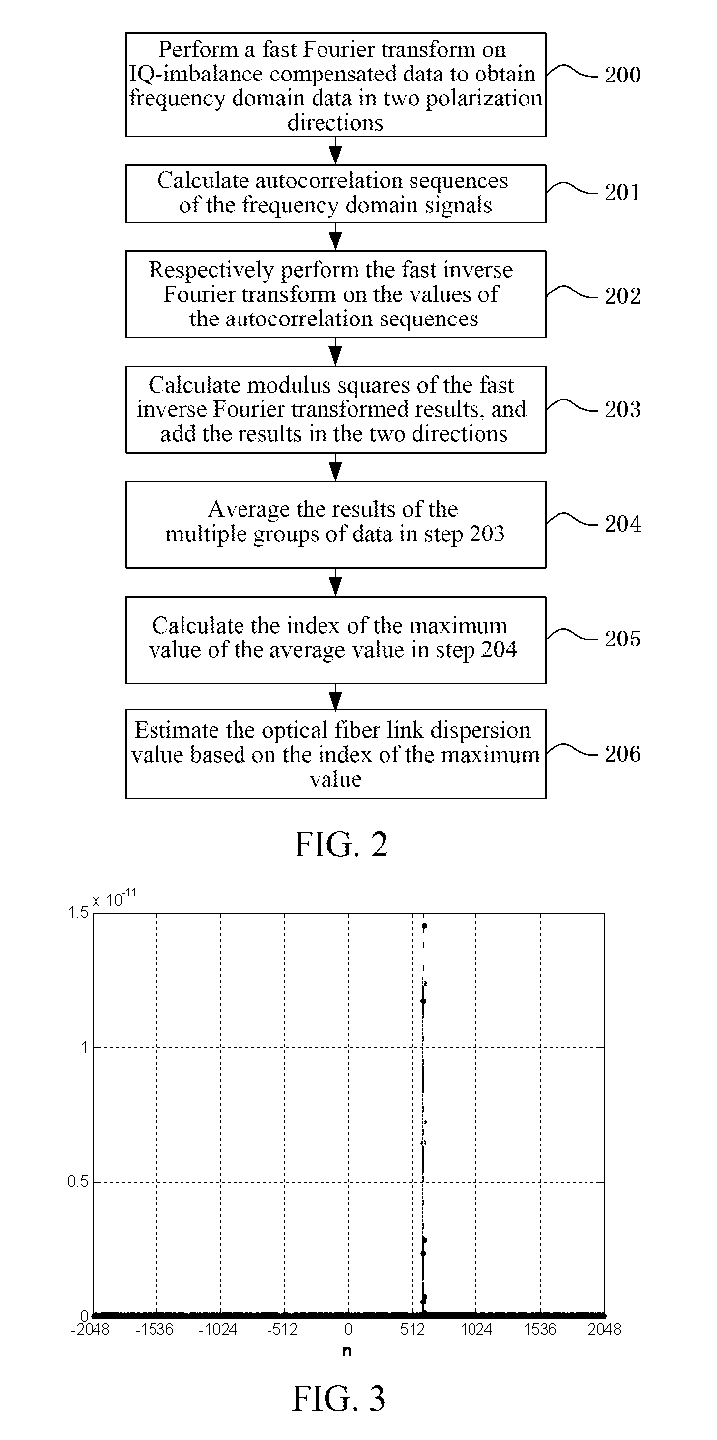
[0082]The embodiment of the present invention provides a dispersion estimation method in optical coherent communication, and as shown in FIG. 2, it comprises the following steps:

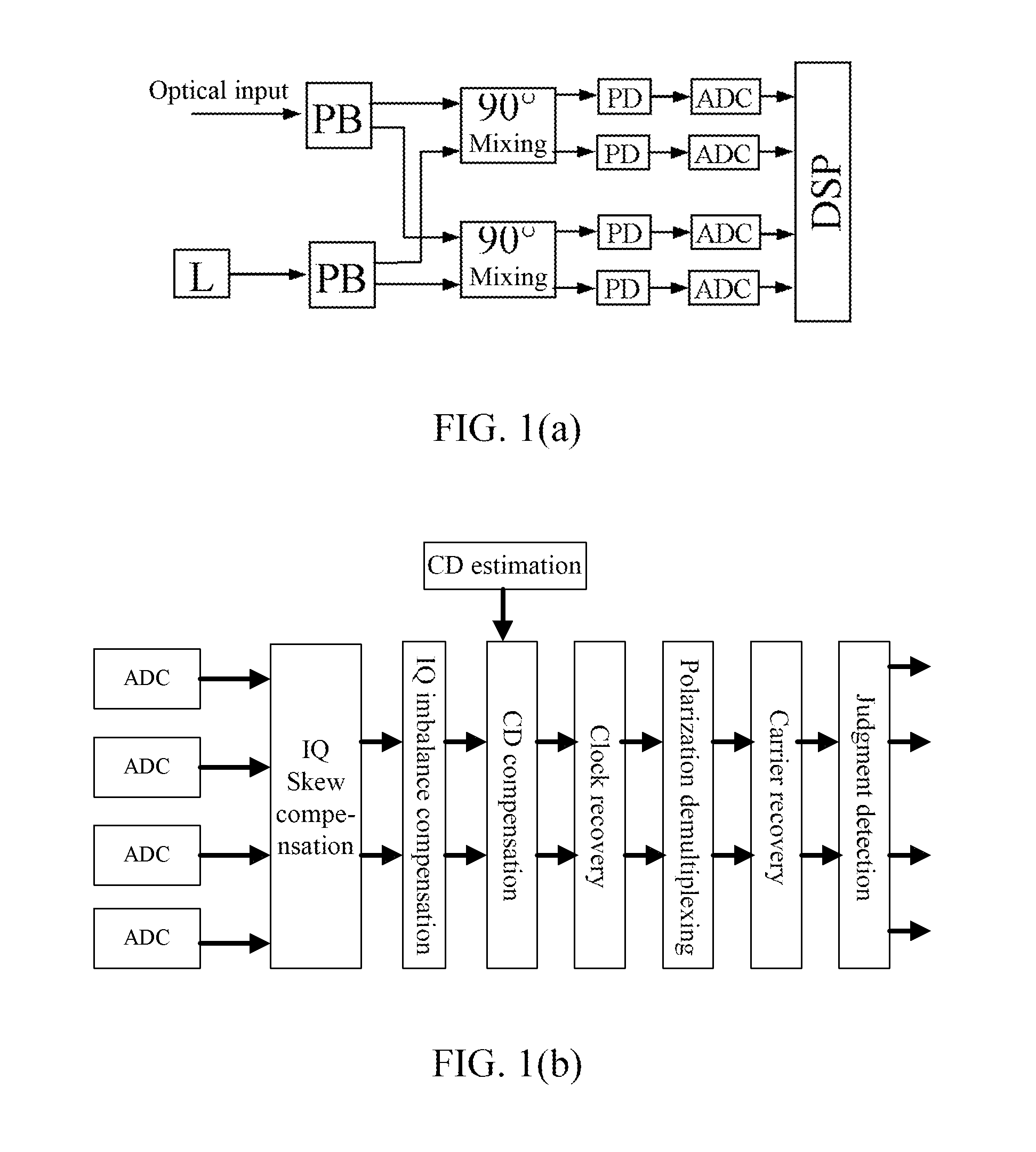
[0083]in step 200, it is to perform a fast Fourier transform on IQ-imbalance compensated data to obtain frequency domain data in two polarization directions;

[0084]Usually, the dispersion compensation module uses the frequency domain convolution technology, and can provide frequency domain data for the CD estimation module. Or, the CD estimation module separately performs FFT on the IQ-imbalance compensated time domain signal to obtain frequency domain data.

[0085]For the polarization multiplexing digital coherent receiver, there are two orthogonal polarization states, the frequency domain signals

[0086]X[k] and Y[k], k=0, . . . , Nfft−1 are respectively calculated.

[0087]wherein k is the frequency index, Nfft is the number of Fourier transform points, the frequency interval is Δf=Ts / Nfft, wh...

second embodiment

The Second Embodiment

[0107]The embodiment of the present invention further comprises a dispersion estimation device in optical coherent communication, as shown in FIG. 6, comprising at lease one processer executing a dispersion compensation unit 601 and a dispersion estimation unit 602, wherein:

[0108]the dispersion compensation unit 601 is configured to: perform the fast Fourier transform on IQ-imbalance compensated data to obtain frequency domain data in two polarization directions;

[0109]the dispersion estimation unit 602 is also divided into a first module 6021, a second module 6022 and a third module 6023, wherein:

[0110]the first module 6021 is configured to: respectively calculate autocorrelation sequences of the IQ-imbalance compensated and fast Fourier transformed frequency domain data in the two polarization directions;

[0111]the abovementioned first module 6021 is configured to: according to the following equation, calculate the autocorrelation sequence C1[k] of the spectrum ...


PUM


Abstract

Disclosed are a chromatic dispersion estimation method and device in optical coherent communication, wherein, the method includes: performing a fast Fourier transform on IQ-imbalance compensated data to obtain frequency-domain data in two polarization directions; calculating autocorrelation sequences of the frequency-domain data and performing an inverse fast Fourier transform on the values of the autocorrelation sequences; calculating modulus squares of the results of the inverse fast Fourier transform, and adding the results in the two polarization directions to obtain; determining a mean value of s of a plurality of data sets; calculating an index of the maximum value of, and estimating a dispersion value of the optical fiber link according to the index of the maximum value of. The abovementioned technical solution allows a significantly accurate and rapid estimation of dispersion values.

Description

CROSS-REFERENCE TO RELATED APPLICATION(S)[0001]This application is the U.S. National Phase application of PCT application number PCT / CN2014 / 078327 having a PCT filing date of May 23, 2014, which claims priority of Chinese patent application 201310498534.7 filed on Oct. 22, 2013, the disclosures of which are hereby incorporated by reference.TECHNICAL FIELD[0002]The present invention relates to the field of chromatic dispersion estimation technologies in the optical coherent communication, and more particularly, to a chromatic dispersion estimation method and device in the optical coherent communication.BACKGROUND OF RELATED ART[0003]With the increase of Internet traffic, larger capacity is needed in the optical communication system of the trunk system. When the bit rate per wavelength increases, the chromatic dispersion, polarization mode dispersion, and waveform distortions of various non-linear effects in the transmission path result in serious degradation in the quality of the inf...

Claims


Application Information

Patent Timeline
Patent Type & Authority Applications(United States)
IPC IPC(8): H04B10/079H04B10/61
CPCH04B10/07951H04B10/612H04B10/6161H04B10/613H04B10/6163H04B10/6165H04B10/6166
Inventor YAO, YANGZHONGLI, QIANGLI, YUNPENGGU, GUOHUAREN, WEI
Owner SANECHIPS TECH CO LTD
Why Eureka
Try Eureka