Composite Material

a technology of composite materials and materials, applied in the field of composite materials, can solve the problems of high manufacturing cost, higher wear resistance, and complex rigid connection structure, and achieve the effects of reducing manufacturing costs, improving manufacturing efficiency, and improving service li

Inactive Publication Date: 2016-10-06
LGARDE
View PDF2 Cites 12 Cited by
  • Summary
  • Abstract
  • Description
  • Claims
  • Application Information

AI Technical Summary

Benefits of technology

[0011]Embodiments described herein include a flexible, lightweight, composite material that can be used as a deployable structure having a low stowed volume, but still meet structural requirements.

Problems solved by technology

However, rigid connections are generally more complex in construction, which results in higher manufacturing costs.
Rigid connections may also be subject to higher wear, and lower accuracy and repeatability.
Moreover, the components generally include dissimilar materials resulting in different coefficients of thermal expansion, high density, and higher weight.
Further, in all the above joints, there is relative motion causing friction that leads to wear and increased clearances.
A kinematic chain of such joints compounds the individual errors from backlash and wear, resulting in poor accuracy and repeatability.
However, compliant structures generally do not provide sufficient rigidity, are not sufficiently thermally stable, or only have narrow ranges of operational temperatures.
However, in many applications today, such as eyewear, robots, scissors, toys, prostheses, etc., rigid-body mechanisms are still used because the resulting compliant materials lack the right balance of mechanical properties.
Although they have low density and large strain in bending, the limitations of such materials are that they are not sufficiently stiff, not thermally stable, and only have narrow operational temperature ranges.
However, such materials require controlled temperatures for stowing and deploying.
The added devices to heat and / or cool the material to the necessary temperatures add system complexity, weight, and cost to actuate the deployable structure.
The main limitation of this kind of actuated composite is that the temperature needs to be precisely monitored and tailored in a controllable environment in order to properly activate the actuated composite.
This means that an external energy source and additional equipment is needed that will not only add cost and mass, but could introduce geometric imperfections such as straightness imperfections due to thermal effects.
These imperfections can degrade axial stiffness and therefore bending stiffness in structures.
Accordingly, active hinges add weight and complexity to any structure.
In addition, in spite of the various technology advances in the area of lightweight deployable structures during the last ten years, a decrease in material density continues to be the most important and challenging parameter in achieving increased performance and functionality.
However, current large systems are also limited by stowed volume.

Method used


Image

  • Composite Material
  • Composite Material
  • Composite Material

Examples


Embodiment Construction

[0045]The following detailed description illustrates by way of example, not by way of limitation, the principles of the invention. This description will clearly enable one skilled in the art to make and use the invention, and describes several embodiments, adaptations, variations, alternatives and uses of the invention, including what is presently believed to be the best mode of carrying out the invention. It should be understood that the drawings are diagrammatic and schematic representations of exemplary embodiments of the invention, and are not limiting of the present invention nor are they necessarily drawn to scale.

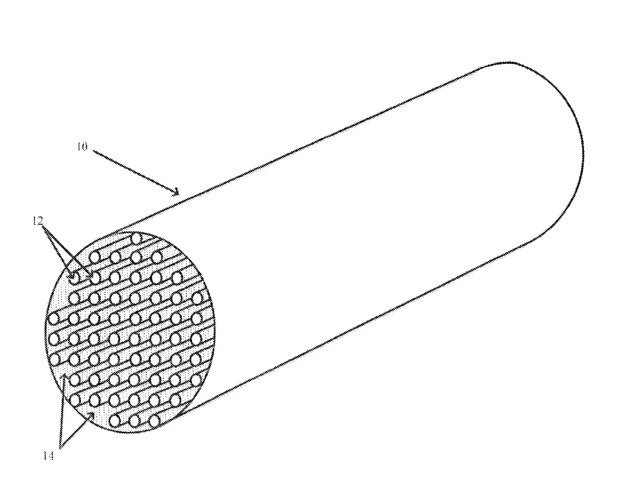
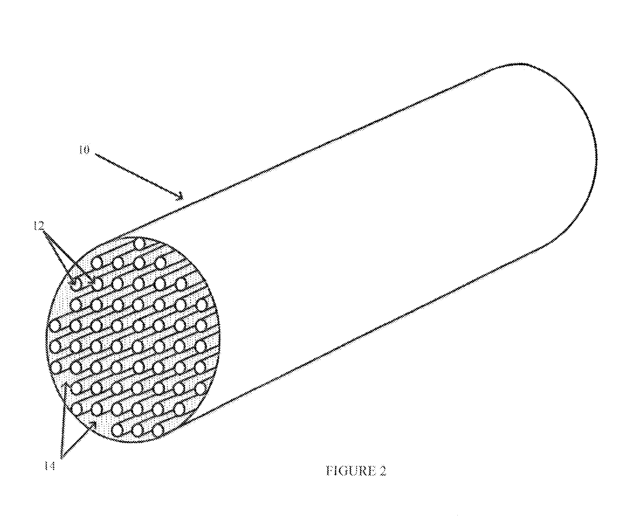
[0046]Embodiments of the composite structures described herein may include properties that can increase reliability and structural performance while reducing the mass and complexity of a system. For example, desired properties may include low coefficients of thermal expansion and low density, while maintaining sufficient structural stiffness or rigidity.

[0047]Althoug...


PUM

PropertyMeasurementUnit
volume fractionaaaaaaaaaa
densityaaaaaaaaaa

Abstract

A unidirectional elastomeric composite comprises a plurality of fibers generally aligned in a first direction with an elastomer filling the space between fibers. The plurality of fibers may comprise an intermediate modulus carbon fiber. Preferably, the plurality of fibers have an ultimate elongation at failure or tensile failure strain of 1% or greater, a tensile modulus between 200-400 GPa and tensile strength greater than 4 GPa. The resin or matrix may be a passive elastomer that will maintain its mechanical and chemical properties at a specific operational temperature range. Elastomers are polymers with viscoelasticity, generally having low Young's modulus and high failure strain. Methods of manufacturing the unidirectional elastomeric composite include apply the resin to fibers maintained in tension to maintain the fiber alignment.

Description

CROSS REFERENCE TO RELATED APPLICATIONS[0001]This application claims priority to U.S. Provisional Application 61 / 900,882, filed Nov. 6, 2013, and titled “Flexible Lightweight Adjustable Stiffness Hinge (FLASH),” which is incorporated by reference in its entirety herein.BACKGROUND[0002]Deployable structures are generally those that can reduce or increase their original volume by packaging or deploying into a smaller volume, respectively. Different material and mechanical structures are used in deployable structures.[0003]For example, rigid mechanical connections allow different kinematic degrees of freedom between rigid connected parts. Compliant joints and mechanisms generally use flexible materials to deform to a desired configuration. However, rigid connections are generally more complex in construction, which results in higher manufacturing costs. Rigid connections may also be subject to higher wear, and lower accuracy and repeatability. Moreover, the components generally include...

Claims


Application Information

Patent Timeline
Patent Type & Authority Applications(United States)
IPC IPC(8): B32B5/12B29C70/20B32B25/20B32B7/02B32B5/02B32B25/02
CPCB32B5/12B29L2031/22B32B25/02B32B25/20B32B7/02B29C70/207B32B2262/106B32B2307/51B32B2307/54B32B2307/536B32B2307/30B29K2083/00B29K2307/04B29K2995/0012B29K2995/0077B29K2995/007B32B5/024B32B5/08B32B5/00B32B5/02B32B5/04B32B7/00B32B2262/00B32B2262/02B32B2262/0207B32B2307/50B32B2307/732B32B2457/00B32B2553/00B32B2605/00C08J5/046C08J2375/04C08J2383/04
Inventor MEJIA-ARIZA, JUAN M.
Owner LGARDE
Why Eureka
Try Eureka