This dispersion of the electrodes and sensors may make the set-up of the
system time-consuming and the subsequent use of the
system cumbersome, which may generate discomfort to the
surgical team during
surgery.
It can even lead to surgeons and / or anaesthesiologists disregarding these systems during
surgery.
Having such a plurality of cables between the monitor and the patient may be annoying for the surgical staff and may be a source of problems during
surgery.
For example, somebody may accidentally stumble into / over a cable and / or a tangle of cables may occur.
This may cause detachment of an electrode / sensor from the patient and / or disconnection of the cable from the monitor.
This may be labour-intensive, time-consuming and cumbersome for the anaesthesiologist and may generate inefficiencies and / or deficiencies in the process of relaxation (i.e. the initial induction, subsequent maintenance, and eventual reversal of a
drug-induced neuromuscular
blockade status) of the patient.
Since the above method of monitoring (or testing) a neuromuscular blockade status highly depends on the attention paid by the anaesthesiologist, a
delay between achievement of a neuromuscular status and corresponding actions on the monitor may occur.
Delayed actuations may generate inefficiencies in terms of e.g. extending the occupation of an operating room, using greater amounts of
muscle relaxant than really needed, etc.
Furthermore, in an Operating Room, momentary situations of
high stress may exist so that an anaesthesiologist may miss the result of a precise electro-stimulation or may lose track of how many stimulations have been performed and previous results.
Said dependence on the anaesthesiologist's attention may also cause the anaesthesiologist to act erroneously on the monitor as a consequence of e.g. a wrong derivation of a
muscle response from the displayed data.
Wrong actuations by the anaesthesiologist may e.g. generate damage or risk of damage to the patient, which have to be attenuated during surgery.
In apparatuses based on obtaining or deriving muscle responses depending on how pressure varies in a pressure
cuff (such as e.g. the one disclosed in U.S. Pat. No. 5,957,860A), patient's heartbeats may create interferences that may distort the
muscle response.
Hence, subsequent actions and / or assessments based on said distorted responses may generate errors in e.g. monitoring (or testing) a neuromuscular blockade status for a patient.
A risk of this structure may be that the conductive layer may be torn or damaged at the level of the region of contact with the patient's
skin and, therefore, the
electrically conductive medium may come into direct contact with the
skin.
In this situation, the patient may thus not be able to alert the
medical team about the damage he / she is suffering.
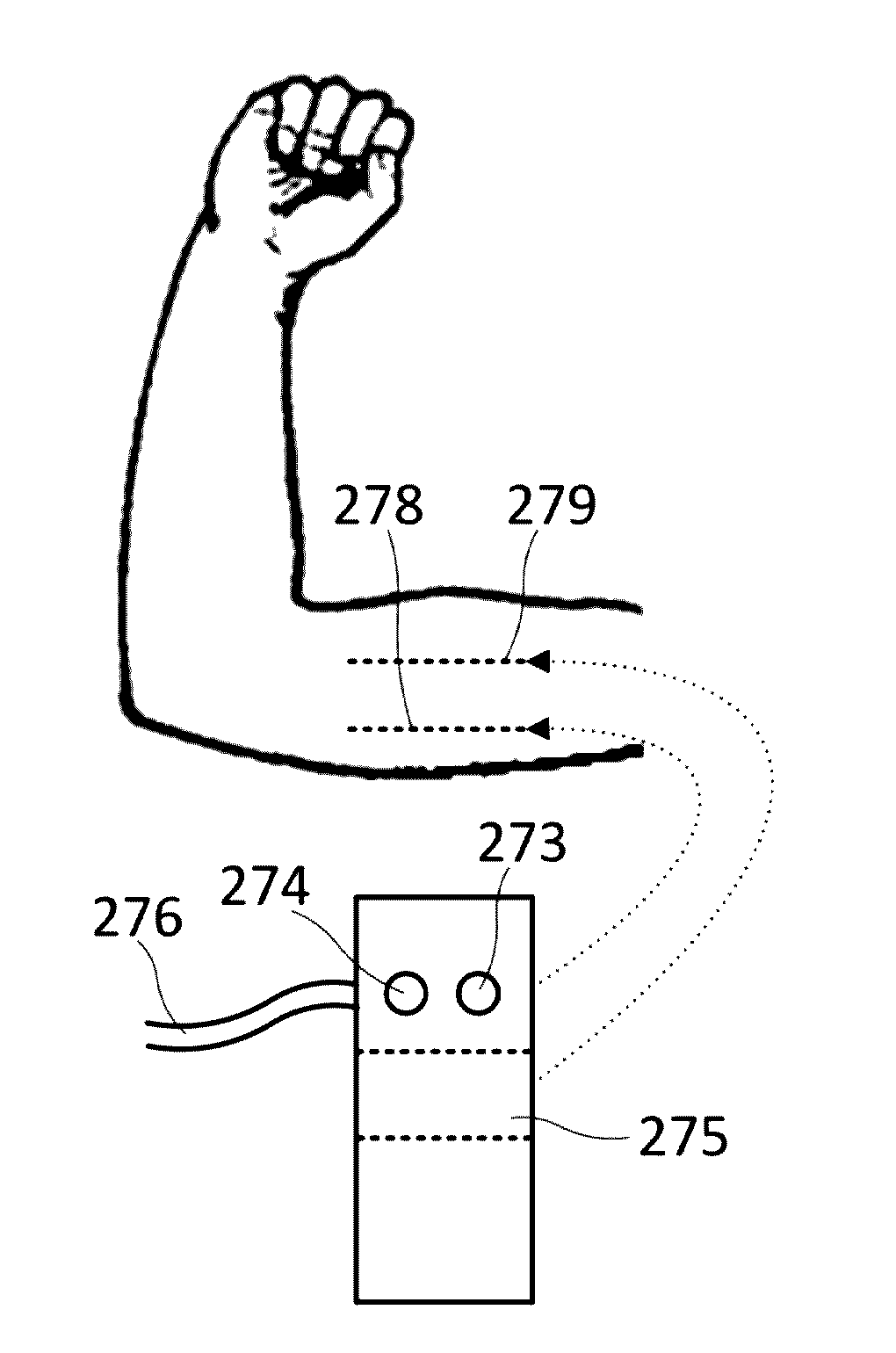
a) transmission of electrical stimuli emitted from a monitor and conveyed through conductive wires electrically connecting the monitor to the pressure cuff, for finally discharging the electrical stimuli onto the patient's skin through corresponding electrodes.
b) entry of pressurized air into the bag of the compressive armband during the inflation phase thereof, and subsequent free evacuation of the air to e.g. the monitor and, from there, to the
atmosphere.
c) pneumatic
air tightness of the connection between the
inflatable bag and the
hybrid connector, without requiring the application of glues, adhesives, or any other type of
sealant of chemical nature. A risk associated with such sealants may be that they can deteriorate over time and, therefore, air leakages may occur. Moreover, UNE-EN ISO 10.993 standards about “Bio-Compatibility of Medical Devices” may not be suitably fulfilled with the use of such sealants.
d) protection against intrusions (of liquids and / or dust) in the junction between the tube and the hybrid connector. Such intrusions can short-circuit the conveyance of electrical stimuli which may put at risk the
physical integrity of the patient and / or surgery staff.
e)
mechanical resistance of the junction between the tube and the hybrid connector without requiring the application of glues, adhesives, or any other type of
sealant of chemical nature. This requirement is aimed at preventing that an excessive pulling of the tube (e.g. accidentally performed by its unnoticed dragging because of the busy circulation of the
operation room's staff around the surgical table) could pull out the tube from its receptacle in the hybrid connector.
f) skin friendly nature since the hybrid connector may rest during surgery on a
delicate skin covering the internal crook of the patient's arm. With this requirement, e.g. skin lacerations or irritations thereto may therefore be prevented.
As shown in Table 1, such an “ACTIVE ON PROXIMAL” arrangement suffers from the important limitation of not being able to warrant an effective evoked
muscle response (TWITCH) after applying (ON) a stimulating current of STRONG intensity on the
motor nerve.
The unnoticed appearance of the “Anodal Block of Conduction” phenomenon may constitute a
potential source of medical errors during the assessment of the neuromuscular blockade condition of a patient, primarily when stimulating a patient's
peripheral motor nerve according to an “ACTIVE ON PROXIMAL” electrodes' set-up with a STRONG
electrical current stimulation intensity.
If no muscle response is obtained, the anesthetist may incorrectly diagnose that the patient is in a deep blockade condition whereas the patient might actually be in a non-blocked condition.
However, as such a reversal operation has to be manually carried out by the practitioner on e.g. a console, monitor or similar, this solution is not failure proof.
This kind of electro-stimulation circuits incorporated in a pressure cuff may be relatively stiff, voluminous, and non-ergonomic, so that they may be annoying to the patient to whom the circuit is applied for electro-stimulation.
Moreover, the fabrication of said circuits may be complicated and time-consuming because a relative large number of manual actions may be required.
The attachment of these electro-stimulation circuits to the pressure cuff may comprise adhesives or similar substances which may cause alterations, such as e.g.
irritation, of the skin of the patient to which the circuit is applied for electro-stimulation.
