
Microreactor-assisted printing of conductive traces with in-situ reactive inks

a technology of reactive inks and microreactors, which is applied in the direction of printed circuits, printed circuit components, conductive pattern formation, etc., can solve the problems of increased cost of sintering processes, tedious synthesis procedures, and additional power sources and facilities for sintering processes

Active Publication Date: 2016-10-13
THE STATE OF OREGON ACTING BY & THROUGH THE OREGON STATE BOARD OF HIGHER EDUCATION ON BEHALF OF OREGON STATE UNIV
View PDF12 Cites 13 Cited by
  • Summary
  • Abstract
  • Description
  • Claims
  • Application Information

AI Technical Summary

Benefits of technology

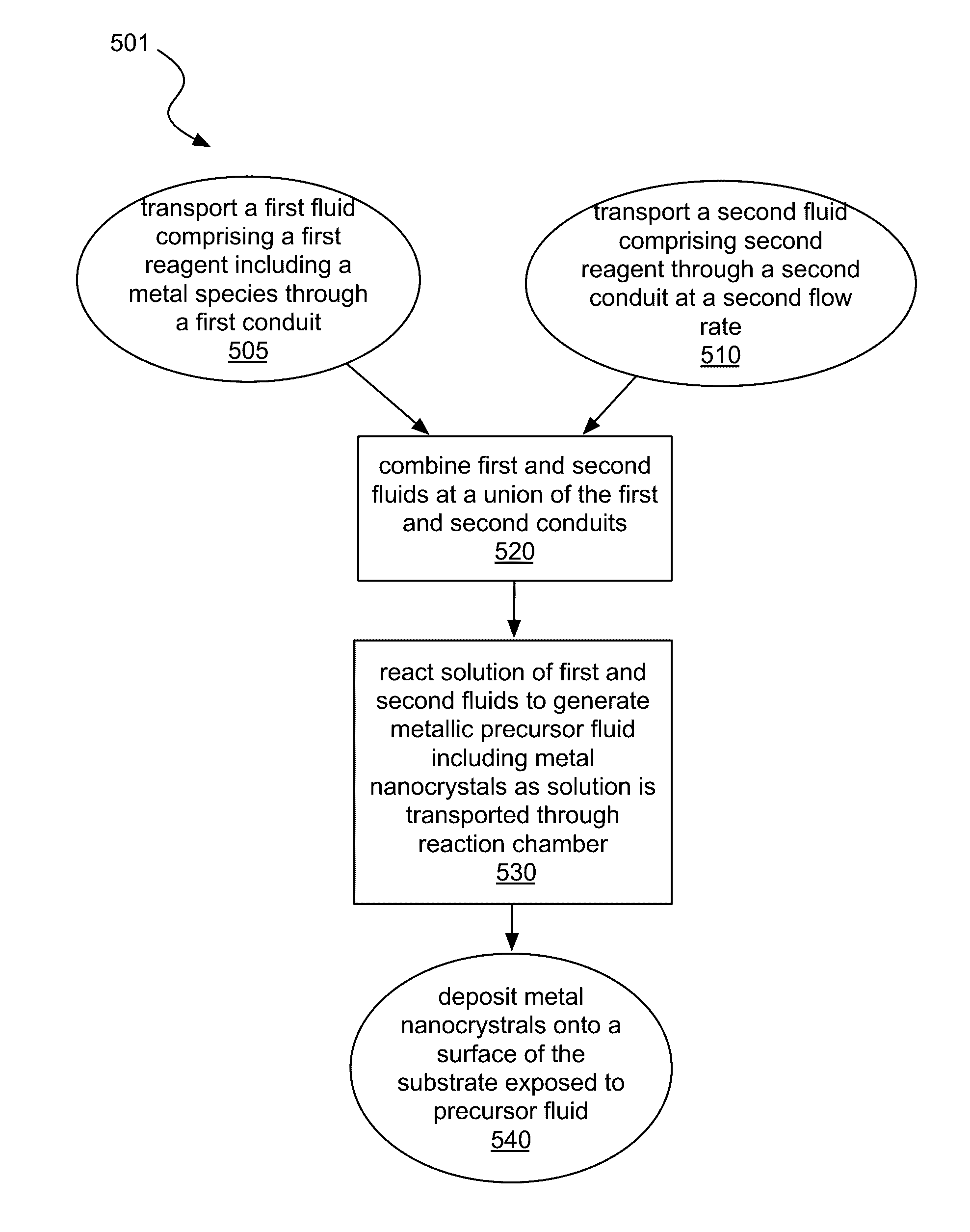
This patent is about a method for making highly conductive silver features using a low-cost and materials-efficient method. The method involves printing silver inks onto a substrate using a micromixer and analyzing the optical properties of the inks. The inks are made using silver nanoparticles and organo-metallic compounds. The method requires a stringent selection of reactants for the synthesis, sufficient stability to ensure ink shelf-life, and tedious synthesis procedures that increased the cost. However, the method offers the advantage of being able to produce highly conductive silver features at relatively low temperatures. The patent also describes a microchannel applicator for printing silver inks. The technical effects of this patent are the development of a method for making highly conductive silver features using a low-cost and materials-efficient method, and the improvement of the sintering process for printing silver nanoparticles.

Problems solved by technology

The synthesis of well-dispersed silver nanoparticle and organic metallic inks suitable for printing and low temperature sintering usually requires the stringent selection of reactants for the synthesis, sufficient stability to ensure ink shelf-life, and tedious synthesis procedures that increased the cost.
In addition, the sintering processes require additional power sources and facilities.

Method used


Image

  • Microreactor-assisted printing of conductive traces with in-situ reactive inks
  • Microreactor-assisted printing of conductive traces with in-situ reactive inks
  • Microreactor-assisted printing of conductive traces with in-situ reactive inks

Examples


Embodiment Construction

[0021]One or more embodiments are described with reference to the enclosed figures. While specific configurations and arrangements are depicted and discussed in detail, it should be understood that this is done for illustrative purposes only. Persons skilled in the relevant art will recognize that other configurations and arrangements are possible without departing from the spirit and scope of the description. It will be apparent to those skilled in the relevant art that techniques and / or arrangements described herein may be employed in a variety of other systems and applications other than what is described in detail herein.

[0022]Reference is made in the following detailed description to the accompanying drawings, which form a part hereof and illustrate exemplary embodiments. Further, it is to be understood that other embodiments may be utilized and structural and / or logical changes may be made without departing from the scope of claimed subject matter. It should also be noted that...


PUM

PropertyMeasurementUnit
Temperatureaaaaaaaaaa
Lengthaaaaaaaaaa
Thicknessaaaaaaaaaa

Abstract

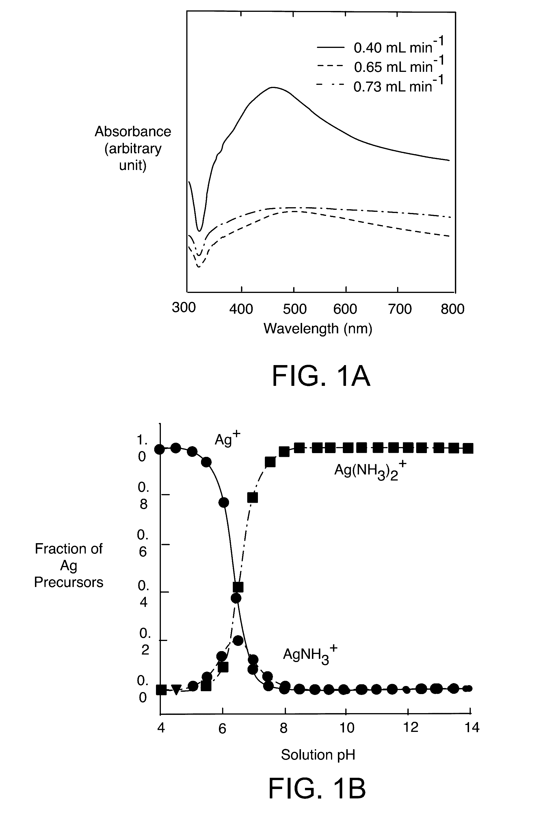
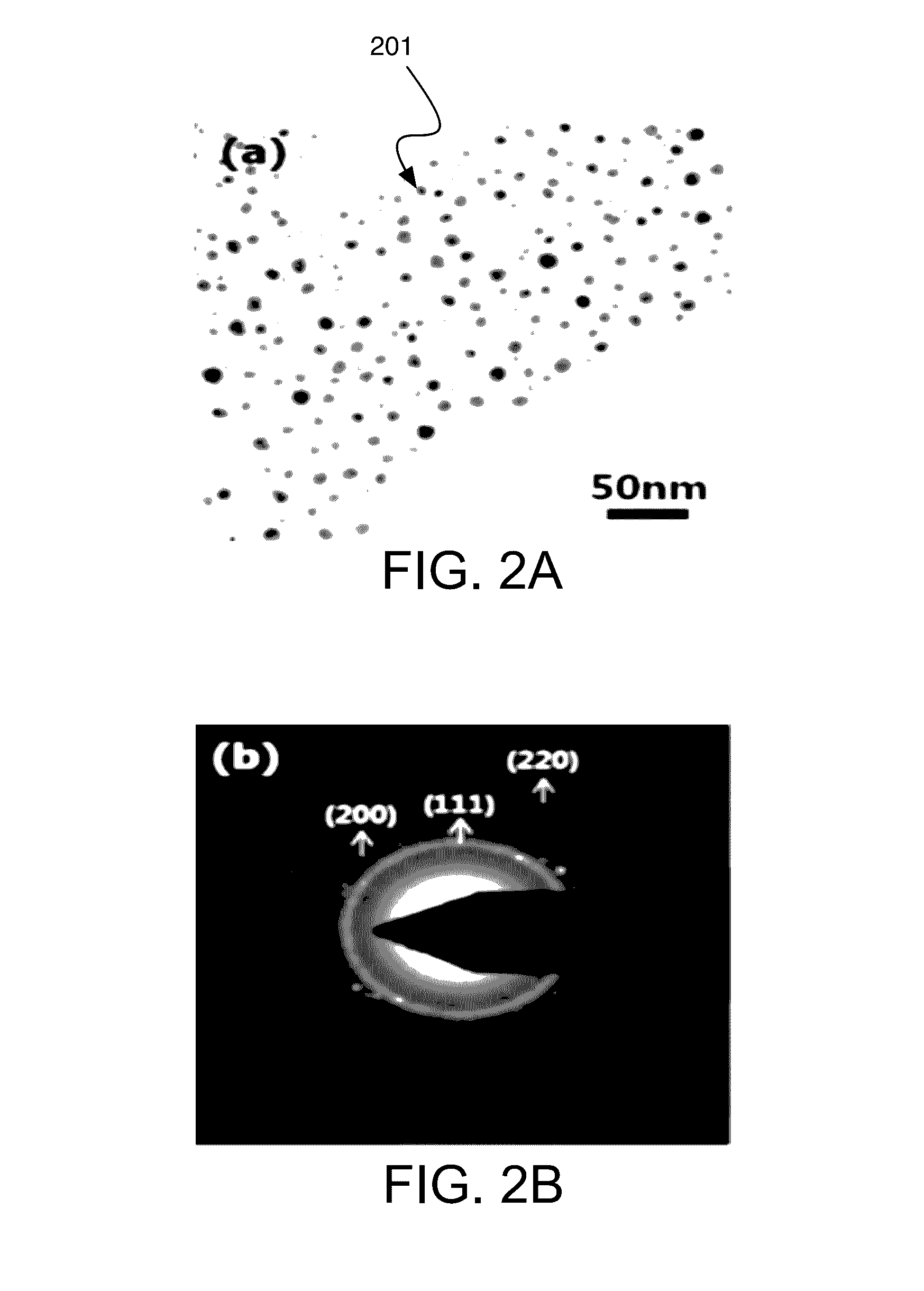
Highly conductive silver may be fabricated at room temperature using in-situ reactive silver precursor inks by microreactor-assisted printing without any post-processing. Reactive silver nanoinks, synthesized in-situ from the microreactor, may be directly delivered onto glass and polymeric substrates without any surface treatment to form a highly dense and uniform silver feature. The distribution of the reactive silver nanoinks can be controlled by adjusting the flow rate of the continuous flow. Silver lines may be fabricated using the in-situ reactive precursors delivered via a micro-channel applicator.

Description

CROSS-REFERENCE TO RELATED APPLICATIONS[0001]This application is a non-provisional application of U.S. provisional application No. 62 / 144,297, filed on Apr. 7, 2015, the subject matter of which is incorporated herein by reference in its entirety for all purposes.GOVERNMENT LICENSE RIGHTS[0002]This invention was made with government support under Grant No. IIP 1439485 awarded by NSF I-Corps. The government has certain rights in the invention.BACKGROUND[0003]Silver possesses excellent electrical conductivity, surface plasmon resonance (SPR), and high reflectivity, leading to a variety of applications such as microelectronic circuitry, gas sensors, low emissivity coating and more recently as transparent conductive electrodes for displays. Since the properties of silver features are closely associated with synthetic approaches, many different synthetic methods have been developed to yield high quality silver features. Direct printing in an atmospheric environment offers a potentially lo...

Claims


Application Information

Patent Timeline
IPC IPC(8): H05K1/09H05K3/00H01L31/02H05K3/12H05K1/03
CPCH05K1/097H05K3/12H05K1/0346H05K1/0393H05K2201/0257H05K3/0085H05K2201/0154H05K2203/0786H01L31/02008H05K3/1241H05K2203/1157H01L31/022425Y02E10/50
Inventor CHANG, CHIH-HUNGCHOI, CHANG-HO
Owner THE STATE OF OREGON ACTING BY & THROUGH THE OREGON STATE BOARD OF HIGHER EDUCATION ON BEHALF OF OREGON STATE UNIV
Learn More