Aircraft propulsion system

a propulsion system and aircraft technology, applied in the field of aircraft propulsion systems, can solve the problems of affecting the performance of the engine, and introducing significant weight into the engine, so as to reduce or increase the soot emissions of the engine, increase or decrease the effect of the soot emissions

Active Publication Date: 2016-10-20
ROLLS ROYCE PLC
View PDF1 Cites 29 Cited by
  • Summary
  • Abstract
  • Description
  • Claims
  • Application Information

AI Technical Summary

Benefits of technology

[0018]The controller may alter engine operation to reduce or increase engine soot emissions according to one or more sensed contrail and / or ambient condition. The controller may increase or decrease engine soot emissions according to a sunlight level determination.

Problems solved by technology

However such equipment potentially introduces significant weight into the engine.
Furthermore, the weight penalty is incurred throughout the full duration of a flight, even though vapour trail suppression may only be required for a small percentage of the flight time.
However the additional energy required to operate the system could represent a significant portion of the engine power and thus incur a fuel-burn penalty.
Further, in military applications, the emission of powerful electromagnetic radiation has the undesirable effect of increasing the aircraft's detectability.
Such solutions present the prospect of additional pollution, incur a weight penalty through the need to carry fuel additives with potentially little or no calorific value of their own, and may present challenges to engine reliability and / or component life.
The strategy of avoiding regions prone to vapour trail formation and / or persistence through the routing of aircraft around, above and / or below such regions has the disadvantage that it increases workload for air traffic control and / or pilots, reduces airspace capacity and, in the case of routing around regions prone to vapour trail formation or persistence (which can be tens or hundreds of kilometers in horizontal extent), the length of the route followed by the aircraft is increased, resulting in a fuel-burn penalty.
Although the primary motivation for such alternative engine configurations is improved efficiency and hence reduced emissions of CO2, it has been found that the exhaust of an isolated engine core is prone to contrail formation over a potentially wider range of altitudes and / or atmospheric conditions than that of a conventional turbofan.

Method used


Image

  • Aircraft propulsion system
  • Aircraft propulsion system
  • Aircraft propulsion system

Examples


Embodiment Construction

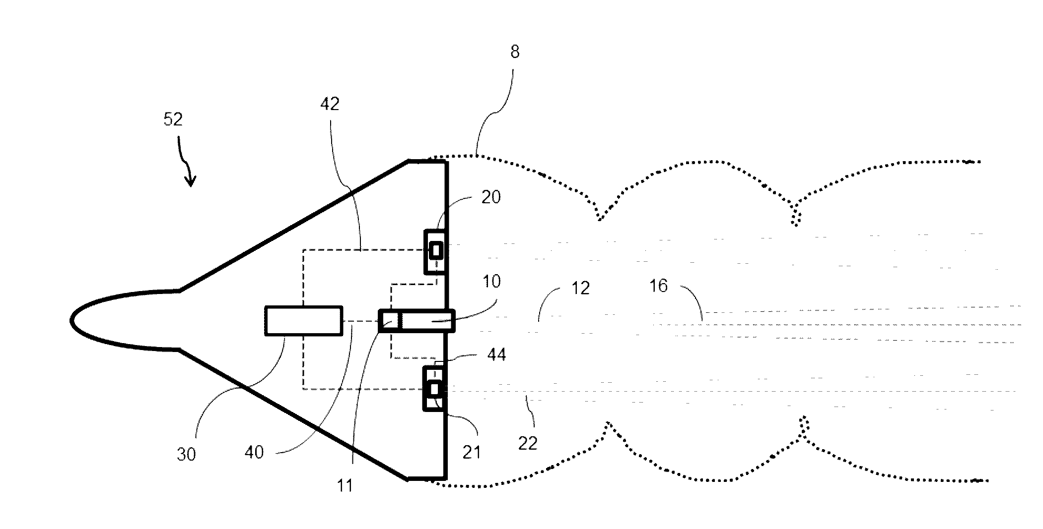
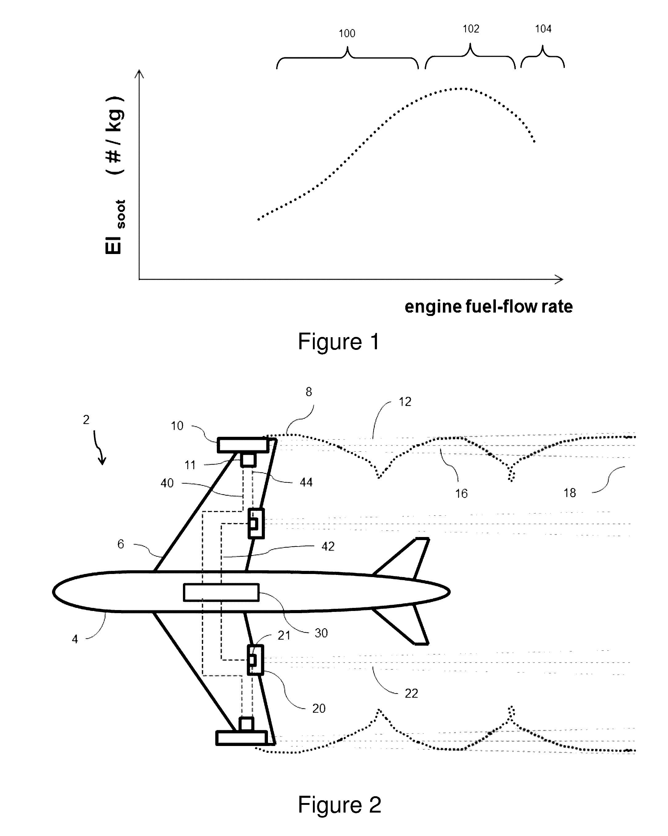
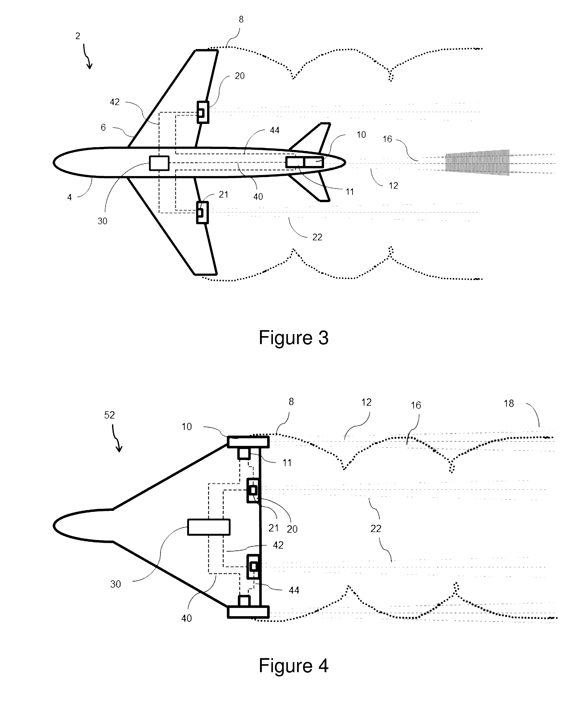
[0036]Contrails, also known as condensation trails or vapour trails, are line-shaped ice clouds which can form in the exhaust plumes of aircraft engines. The climate impact of a contrail depends upon its longevity, its spatial extent and its optical depth, as well as external factors such as the ambient air temperature, and the strength of incoming sunlight, and the albedo of underlying cloud layers and / or surface.

[0037]Contrails reflect incoming sunlight away, exerting a cooling effect (during the day). However, they also absorb outgoing infra-red radiation, leading to a warming impact (day and night). The net effect is a balance of these two effects, and can change during the lifetime of the contrail.

[0038]In ambient air of sufficiently low humidity, a contrail is relatively short lived, disappearing in a timescale of seconds to minutes. However, if ambient air is supersaturated with respect to ice, a contrail can persist for tens of minutes or hours, spreading out over time to re...


PUM


Abstract

An aircraft propulsion system in which a combustion engine is arranged to drive an electrical generator. An electrical energy store is provided within the system. A propulsive rotor is arranged to be driven by an electric motor and a controller selectively varies the supply of power to the electric motor from the generator and/or energy store in dependence on one or more property of a vapour trail resulting from the engine exhaust flow. The controller may also control the supply of power to the energy store for charging.

Description

BACKGROUND OF THE INVENTION[0001]This disclosure concerns aircraft propulsion systems, and more particularly, aircraft propulsion systems in which a propulsive fan is driven by electrical energy derived from an aircraft combustion engine.[0002]Vapour trails are artificial clouds that are visible trails of condensed water vapour caused by combustion products exhausted from aircraft engines. They may be formed as warm, moist exhaust gas mixes with ambient air, and arise from the precipitation of microscopic water droplets or, if the air is cold enough, tiny ice crystals. The term “vapour trails” is intended to refer both to condensation trails (that is to say “contrails”) from aircraft and to water and / or ice precipitation in or attributable to the exhaust plumes from engines.[0003]It is understood that, depending on the timescale considered, the climate-warming impact of aircraft exhaust vapour trails and resulting vapour trail-cirrus may be of a magnitude similar to, or perhaps even...

Claims


Application Information

Patent Timeline
Patent Type & Authority Applications(United States)
IPC IPC(8): B64D31/06B64D45/00B64D27/24
CPCB64D31/06B64D2027/026B64D45/00B64D27/24Y02T50/40Y02T50/60B64D27/02F02C9/56H02K7/18
Inventor SWANN, PETER
Owner ROLLS ROYCE PLC
Why Eureka
Try Eureka