

Electricity generation and water desalinization in constructed shafts utilizing geothermal heat
- Summary
- Abstract
- Description
- Claims
- Application Information
AI Technical Summary
Benefits of technology
Problems solved by technology
Method used
Image

Examples
embodiment 10
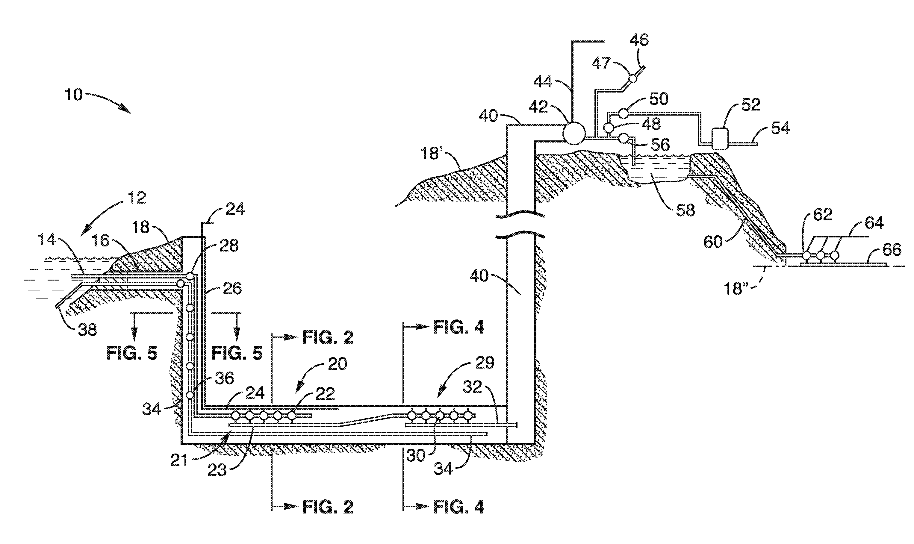
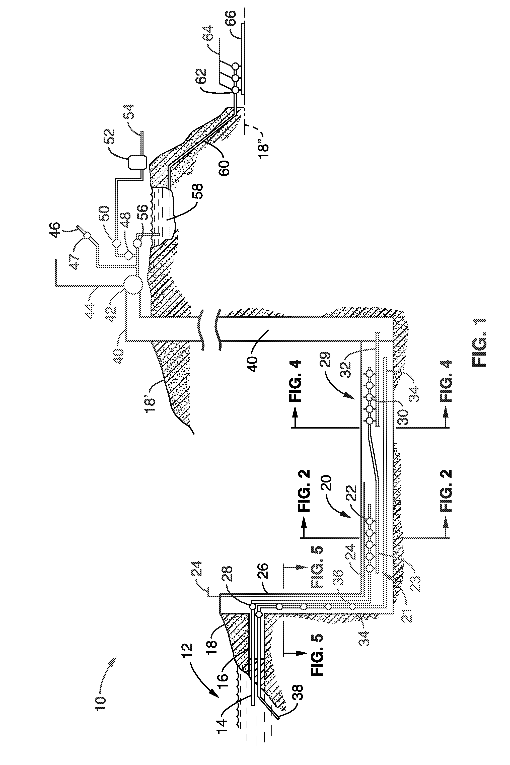
[0054]In the exemplified embodiment 10, the steam output from the desalination process is carried up through a separate shaft 40. It is preferred that this shaft be non-insulated, so that the heat at the bottom of the shaft rises and aids in carrying the steam to the surface of the earth. Thus, it is seen that the distilled water exits the desalination phase and enters the shaft which is not insulated from the Earth's heat allowing this heat to conduct through the shaft material (e.g., concrete tiles, or other suitable material) causing the water to turn into steam under tremendous pressure traveling at speeds possibly in excess of 200 mph towards the surface.
[0055]In at least one embodiment, the steam reaching the surface 18′ is directed through steam turbine generators (turbine coupled to a generator) 42, with the electricity produced being conveyed over power lines 44 to the power grid. It should be appreciated that the earth surface 18′ to where the steam is output, is preferabl...
embodiment 90
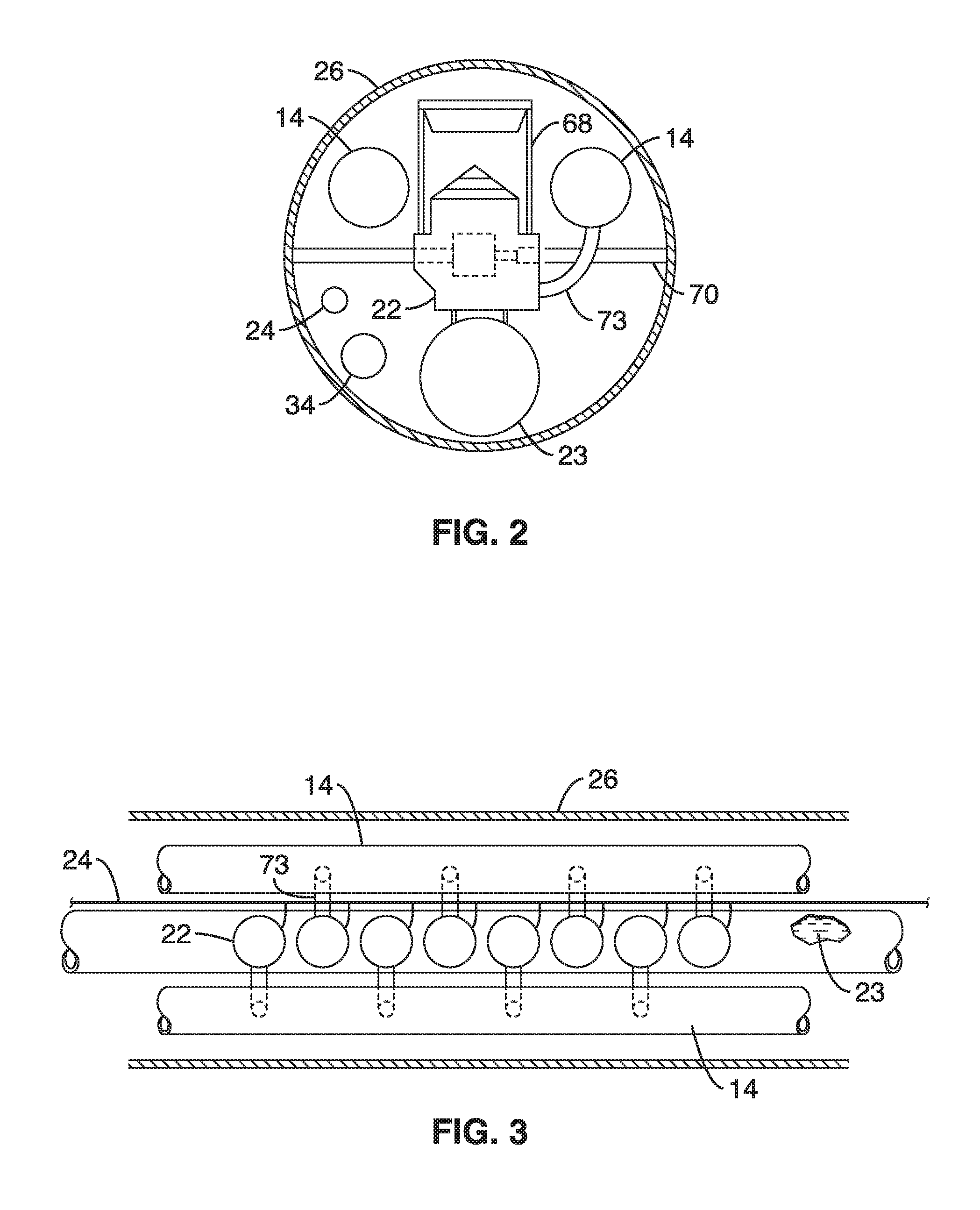
[0064]A side view is seen in FIG. 6 of embodiment 90, showing more clearly the exemplified periodic nature of the support structure 92, 94a, 94b, 96 for the source water pipe 14, as well as the equipment elevator. It can be seen also that flanges 104 connect sequential sections of the source water pipe 14. The shaft 16 is preferably lined with insulated material (e.g., concrete tiles) thermally protecting the inside of the shaft from the Earth's heat at the lower depths. In addition, in at least one embodiment, a crane 68 in FIG. 2 or other form of lifting equipment, such as equipment elevator 100, is included for accessing the entire length of the shaft segment to carry replacement parts to and from the equipment elevator.
[0065]3. Single Shaft Embodiment.
[0066]A simplified embodiment is described below using a single vertical shaft which contains the majority of elements described in the previous sections. In this embodiment, seawater enters the intake pipe from the ocean (freshwat...
PUM
 Abstract
Description
Claims
Application Information