
OLED display panel

a technology of display panel and oled body, which is applied in the field of oled display panel, can solve the problems of oled technology drawbacks, blue light output will decrease relative to the other colors of light, and light degrade significantly faster

Inactive Publication Date: 2016-11-10
FLATFROG LAB
View PDF19 Cites 49 Cited by
  • Summary
  • Abstract
  • Description
  • Claims
  • Application Information

AI Technical Summary

Benefits of technology

The invention is a display panel with pixels that have a first sub-pixel with a first OLED and a first quantum dot structure that emits light at a base wavelength. The first sub-pixel acts as an IR emitter and the first quantum dot structure absorbs the light and emits it at a longer wavelength. The panel also includes an IR detector. The technical effects of the invention include improved touch sensing, reduced power consumption, and improved display quality.

Problems solved by technology

However, there are also drawbacks related to the OLED technology.
For one thing, the OLEDs tend to age, meaning that they degrade over time.
More particularly, OLED materials used to produce blue light degrade significantly more rapidly than the materials that produce other colors, and therefore blue light output will decrease relative to the other colors of light.
This can be partially avoided by adjusting color balance but this may require advanced control circuits and interaction with the user, which is unacceptable for some users.

Method used


Image

  • OLED display panel
  • OLED display panel
  • OLED display panel

Examples


Embodiment Construction

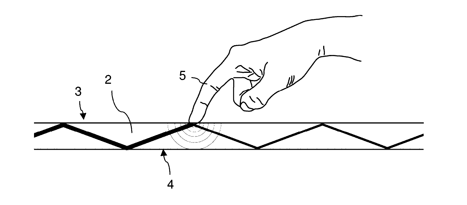
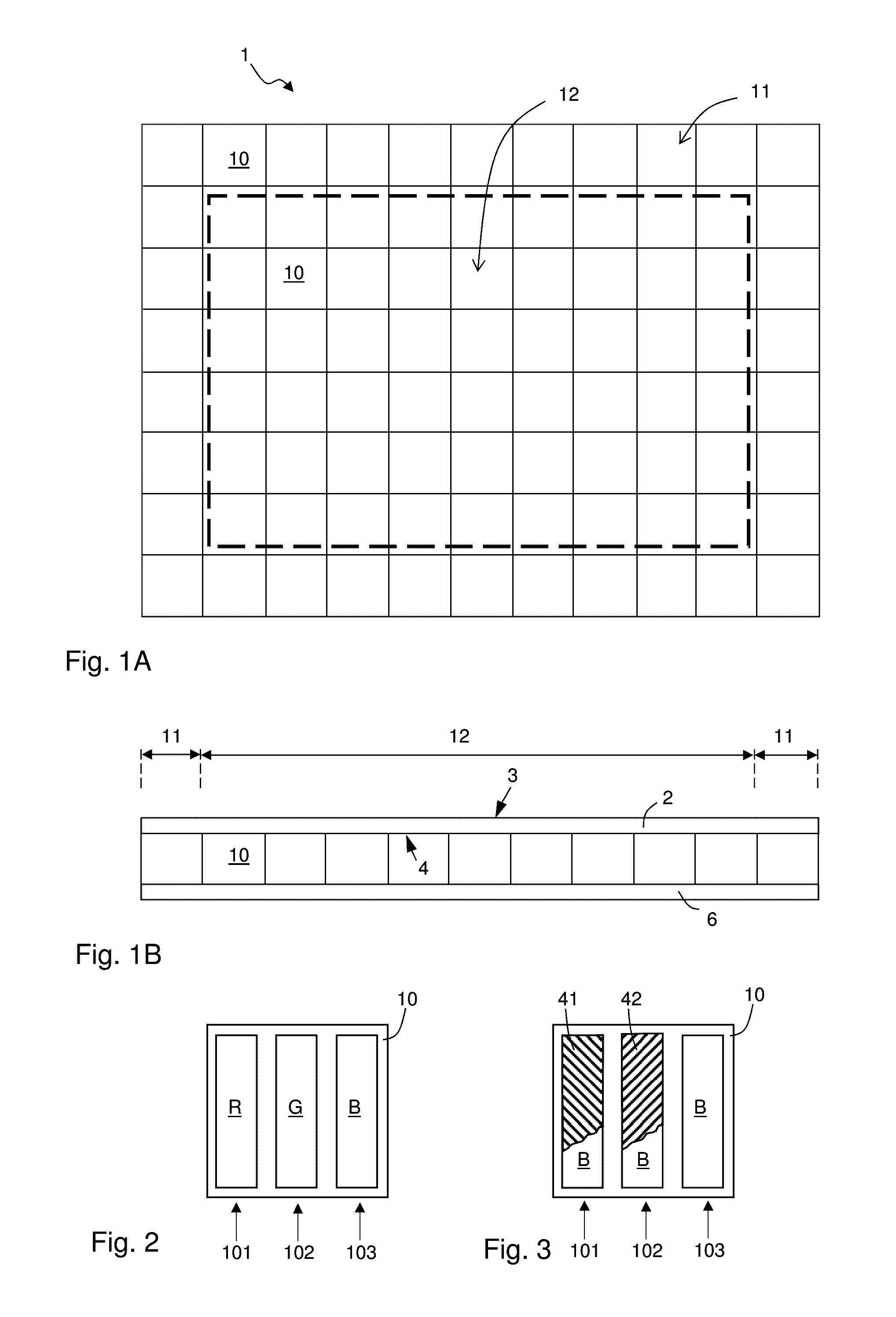
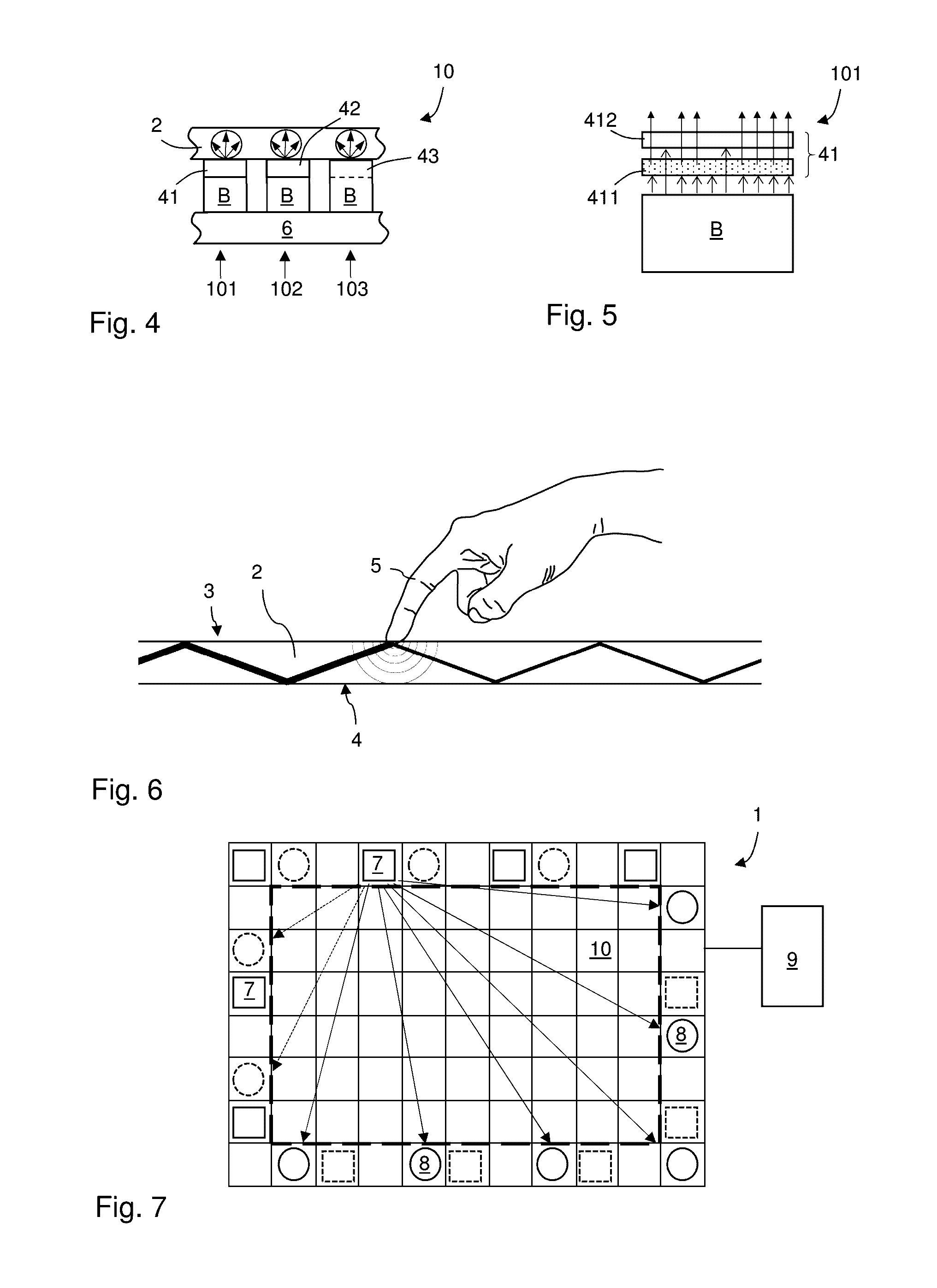
[0063]The present invention relates, in its broadest sense, to solutions for generating light of different wavelength ranges from an OLED display, by providing a pixel configuration incorporating a quantum dot structure. Various embodiment will be described on a functional level, sufficient for carrying out the claimed embodiments. However, the different ways of designing an OLED, including its detailed inner structure, is as such not crucial for the function or reproduction of the invention. Furthermore, the OLED technology is mature and well described in the art, and no detailed description of the OLED technology will hence be given herein. On a general level of description, though, an OLED comprises a rear electrode, e.g. an anode, and a front electrode, e.g. a cathode, and an intermediate organic structure formed by one or plural organic layers. The front electrode layer is transparent and may e.g. be made of indium tin oxide (no).

[0064]FIG. 1A schematically illustrates a top pl...


PUM


Abstract

A display panel with a plurality of pixels, including a pixel of a first pixel configuration with a first sub-pixel, which comprises: a first OLED configured to emit light at a base wavelength, and a first quantum dot structure disposed over the first OLED, configured to absorb light of the base wavelength so as to emit light at a first longer wavelength. Embodiments include a touch-sensing display panel, where the first quantum dot structure is configured to emit IR light into a light guide having a front surface forming a touch-sensing region and an opposite rear surface facing the pixels, wherein said IR emitter is optically connected to emit light into the light guide for propagation therein through total internal reflection in at least the front surface; and an IR detector connected to receive propagated light from the light guide.

Description

CROSS-REFERENCE TO RELATED APPLICATIONS[0001]The present application claims the benefit of Swedish patent application No. 1450036-7, filed 16 Jan. 2014.TECHNICAL FIELD[0002]The present invention relates to display panels, and specifically to pixel structures for obtaining light of different wavelengths.BACKGROUND ART[0003]While the early years of display technology were dominated by the cathode ray tube (CRT) technology, the first flat display panels were presented more than 50 years ago and dominate the market today. For television purposes, plasma type displays and Liquid Crystal Display (LCD) were the first to gain market share from CRT monitors. In recent years, a display technology that has grown to be a valid competitor to the LCD technology is based on the Organic Light Emitting Diode (OLED). The basic structure of an OLED is a cathode, which injects electrons, and an anode, and in between the two an organic emissive layer where electrons and electron holes re-combine under t...

Claims


Application Information

Patent Timeline
IPC IPC(8): G06F3/042H01L27/32H01L51/52G06F3/041
CPCG06F3/0428G06F3/0416H01L27/322H01L27/323H01L2251/5369H01L27/3218H01L51/5271H01L27/3213G06F2203/04109H01L51/5262G09G3/32G09G2300/0452G09G2320/0242G09G2320/043H10K59/38H10K59/40H10K59/8791H10K50/85H10K50/856H10K59/351H10K59/353H10K2102/331
Inventor KLINGHULT, GUNNAR
Owner FLATFROG LAB
Learn More