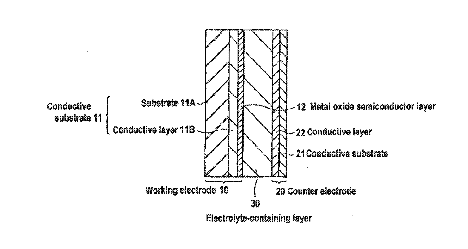
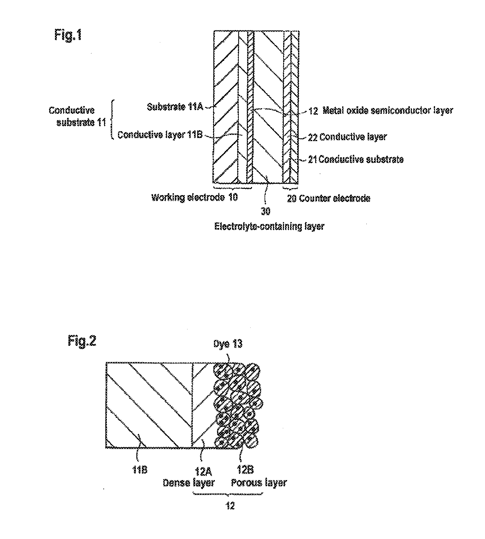
Carrier system and photoelectric conversion device

a carrier system and photoelectric conversion technology, applied in the field of carrier system and photoelectric conversion device, can solve the problems of low light utilization efficiency and low photoelectric conversion efficiency of the device, and achieve the effect of excellent photoelectric conversion efficiency and suitable for solar cells

Inactive Publication Date: 2016-11-10
ADEKA CORP
View PDF1 Cites 0 Cited by
  • Summary
  • Abstract
  • Description
  • Claims
  • Application Information

AI Technical Summary

Benefits of technology

[0019]A photoelectric conversion device using the carrier system of the invention exhibits excellent photoelectric conversion efficiency and is suitable for solar cells etc.

Problems solved by technology

Unfortunately, dye-sensitized photoelectric conversion devices have the following problem: the absorption wavelengths of sensitizing dyes are limited compared to that of silicon, and therefore, the light utilization efficiency thereof is low, which results in a low photoelectric conversion efficiency of the devices.

Method used


Image

  • Carrier system and photoelectric conversion device
  • Carrier system and photoelectric conversion device
  • Carrier system and photoelectric conversion device

Examples


synthesis example 1

Synthesis of Compound No. 1

[0116]1-Methylimidazole (Tokyo Chemical Industry Co., Ltd.) (5.07 mmol), 11-iodoundecanoic acid (6.09 mmol), and tetrahydrofuran (6 g) were placed in a reaction flask and were reacted by heating under reflux for 3 hours. Then, hexane was added to the reaction flask, and the precipitated crystals were filtered to obtain 1.33 g of a white solid (yield: 67%). It was verified by 1H-NMR and IR that the obtained solid was Compound No. 1. Data are shown in Tables 1 to 3.

synthesis examples 2 to 8

Synthesis of Compounds Nos. 2 to 4 and 19 to 22

[0117]Compounds Nos. 2 to 4 each were synthesized according to the same manner as in Synthesis Example 1, except that an imidazole compound and a haloalkyl carboxylic acid corresponding to the respective target compound were used. Compounds Nos. 19 to 22 were synthesized by subjecting Compound No. 1 to a salt exchange reaction with KPF6, potassium trifluoromethanesulfonate, sodium tetrafluoroborate, and potassium bis(trifluoromethanesulfonyl)imide, respectively. Data are shown in Tables 1 to 3. It should be noted that the yield in each of the Synthesis Examples 5 to 8 is the yield for the salt exchange reaction. Table 4 shows data of 19F-NMR.

TABLE 1YieldSynthesizedAppearance(%)compoundSynthesisWhite solid67No. 1Example 1SynthesisWhite solid48No. 2Example 2SynthesisWhite solid65No. 3Example 3SynthesisWhite solid11No. 4Example 4SynthesisWhite solid98No. 19Example 5SynthesisWhite solid95No. 20Example 6SynthesisWhite solid98No. 21Example 7S...


PUM


Abstract

This carrier carries a pigment (A) and a co-adsorbent (B) represented by the following general formula (1). (In the formula, ring A represents a 5- or 6-membered heterocycle which may be further condensed; the hydrogen atom in ring A may be substituted by a hydrocarbon group which may have a substituent, a halogen atom, a cyano group, a nitro group, a —OR2 group, or a —SR2 group; Z represents a divalent aliphatic hydrocarbon group interrupted 0-3 times by —O— or the like; Z1 represents a divalent aromatic group; R1 represents a carboxylic acid group, a sulfonic acid group, a phosphoric acid group, or a phosphonic acid group; R2 and R3 represent a hydrocarbon group which may have a hydrogen atom or a substituent; Anm− represents an m-valent anion; m represents an integer of 1 or 2; and p represents a coefficient for maintaining a neutral electric charge).

Description

TECHNICAL FIELD[0001]The present invention relates to a carrier system and a photoelectric conversion device provided with an electrode including the carrier system.BACKGROUND ART[0002]Dyes have been widely used in a variety of technical fields so far. In the field of photoelectric conversion devices such as solar cells, for instance, dyes having photosensitizing properties have been used in dye-sensitized photoelectric conversion devices. Dye-sensitized photoelectric conversion devices are expected to theoretically achieve high efficiency and be produced at lower cost than conventional photoelectric conversion devices employing silicon semiconductors. Unfortunately, dye-sensitized photoelectric conversion devices have the following problem: the absorption wavelengths of sensitizing dyes are limited compared to that of silicon, and therefore, the light utilization efficiency thereof is low, which results in a low photoelectric conversion efficiency of the devices.[0003]Methods for s...

Claims


Application Information

Patent Timeline
Patent Type & Authority Applications(United States)
IPC IPC(8): H01G9/20
CPCH01G9/2059H01G9/204H01G9/2031H01G9/2013C09B23/06C09B57/10Y02E10/542Y02P70/50C09B23/00
Inventor AOYAMA, YOHEIAKIMOTO, KENSAKU
Owner ADEKA CORP
Why Eureka
Try Eureka