
Method for the Enhancement of Injection Activities and Stimulation of Oil and Gas Production

a technology for oil and gas production and injection activities, applied in the direction of explosive charges, fluid removal, borehole/well accessories, etc., can solve the problems of plastic deformation of penetrated rock, grain fracturing, and inability to perfect solution, so as to enhance the inflow and/or outflow potential of the inlet and/or outflow, and reduce the fluid pressure. , the effect of enhancing a number of injection activities

Active Publication Date: 2016-11-24
WELLS FARGO BANK NAT ASSOC +1
View PDF4 Cites 5 Cited by
  • Summary
  • Abstract
  • Description
  • Claims
  • Application Information

AI Technical Summary

Benefits of technology

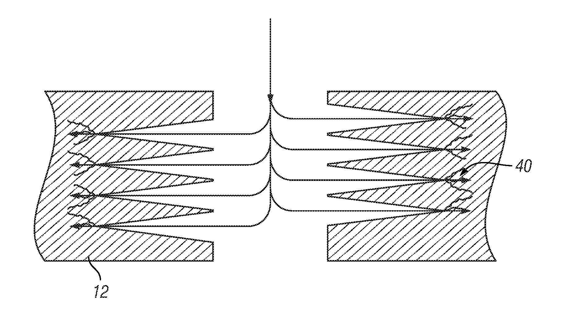
This approach significantly increases perforation efficiency, reduces near-wellbore pressure losses, improves fluid distribution, and lowers the pressure required for hydraulic fracture initiation, resulting in enhanced injection parameters and well productivity.

Problems solved by technology

However, despite these advantages shaped charges provide an imperfect solution.
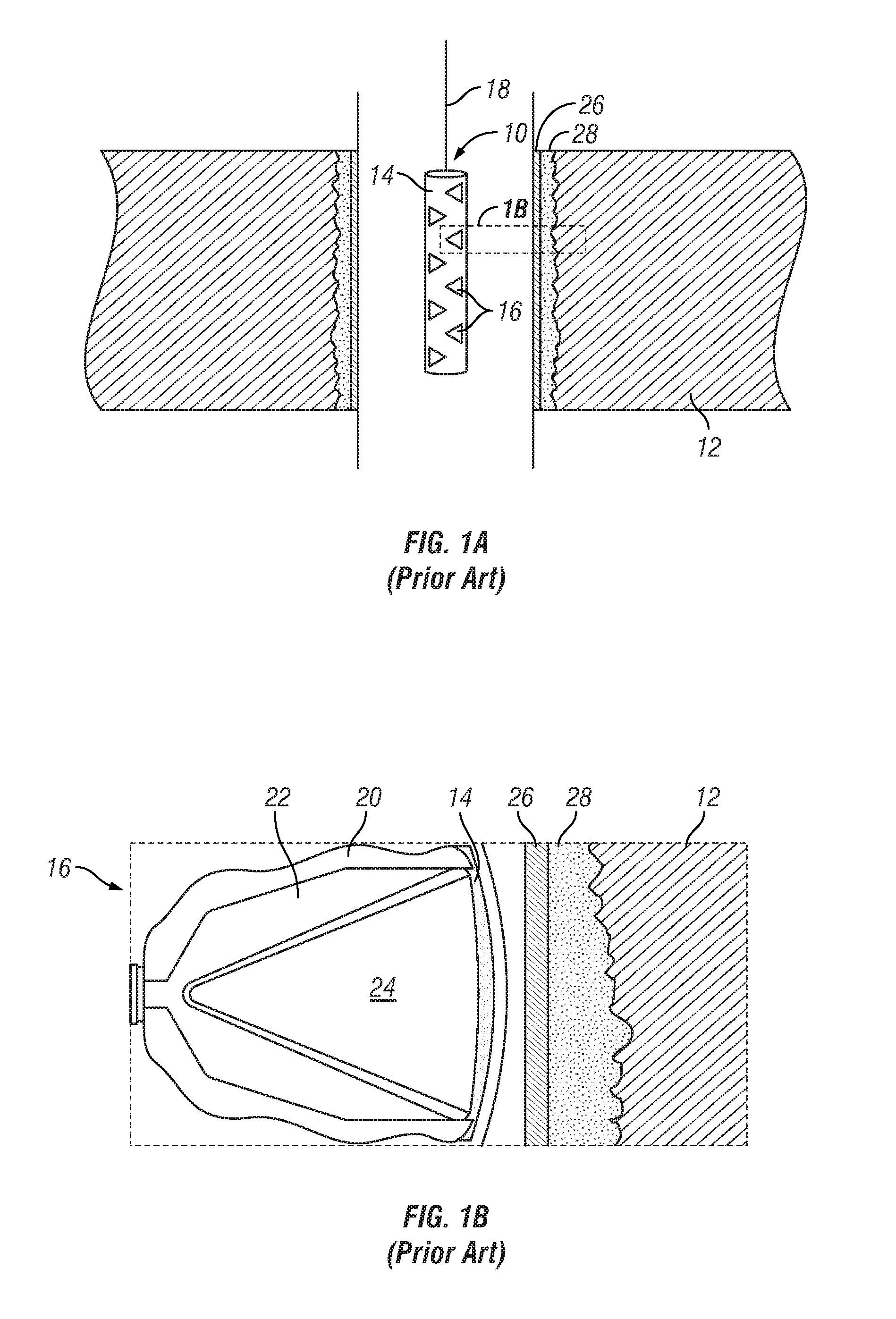
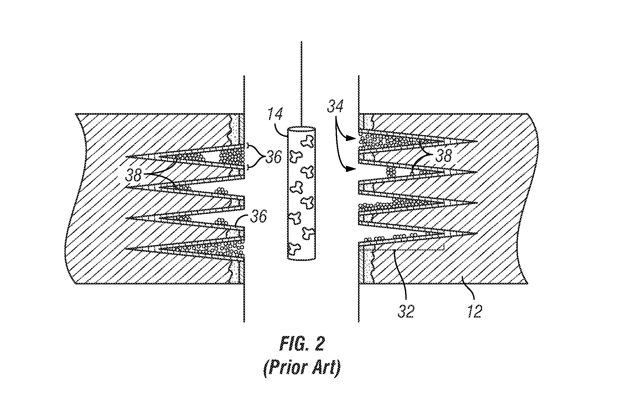
Perforation is inevitably a violent event, pulverizing formation rock grains and resulting in plastic deformation of the penetrated rock, grain fracturing, and the compaction of particulate debris (fractured sand grains, cement particles, and / or metal particles from casing, shaped charge fragments or the disintegrating liner) into the tunnel and the pore throats of rock surrounding the tunnel.
This debris 38 can limit the effectiveness of the created tunnel as a conduit for flow since debris inside the perforation tunnel and embedded into the wall of the tunnel may block the ingress or egress of fluids or gases.
This may cause significant operational difficulties for the well operator and the debris may have to be cleaned out of the tunnels at significant cost.
Plugged tips 30 impair flow and obstruct the production of oil and gas from the well.
The perforating event is so fast that the associated rock deformation and compaction exceed the elastic limit of the rock and result in permanent plastic deformation.
Currently, there is no means of measuring it in the borehole.
This becomes even more significant when near-wellbore formation damage has occurred during the drilling and completion process, for example, resulting from mud filtrate invasion.
If the effective penetration is less than the depth of the invasion, fluid flow can be seriously impaired.
If the reservoir pressure and / or formation permeability is low, or the wellbore pressure cannot be lowered substantially, there may be insufficient driving force to remove the debris.
In heterogeneous formations—where rock properties such as hardness and permeability vary significantly within the perforation interval—and in formations of high-strength, high effective stress and / or low natural permeability, underbalanced techniques become increasingly less effective.
Since the maximum pressure gradient is limited by the difference between the reservoir pressure and the minimum hydrostatic pressure that can be achieved in the wellbore, perforations shot into low permeability rock may never experience sufficient surge flow to clean up.
When properly executed, a hydraulic fracture results in a “path,” connected to the well that has a much higher permeability than the surrounding formation.
However, arriving at an optimum perforation design can be difficult because essentially all perforated completions are damaged, as shown by way of example in FIGS. 2-3.
In extreme cases the altered rock cannot be broken down before surface equipment limitations are reached.
This may result in a tortuous path as depicted in FIG. 4, resulting in increased near-wellbore pressure losses, commonly known as tortuosity.
In FIG. 4, the uneven and inefficient injection and / or stimulation that results with prior art methods is seen.
As chemical solutions are introduced, debris 38 prevents their introduction through plugged tunnels, causing poor coverage across the targeted formation interval.
Furthermore, a high percentage of blocked tunnels means that only relatively few open tunnels will be aligned with the preferred fracture plan, which is determined by the prevailing stress regime in the rock.
Re-orientation of the fracture to the preferred fracture plane after initiating in the direction of the open tunnels will result in additional tortuosity.
Such tortuosity is a primary cause of excessive injection pressure, premature screenout, and incomplete fracture stimulation treatment execution.
Thus, inadequately cleaned tunnels limit the outflow area through which injection fluids can flow; inhibit injection rates at a given injection pressure; impair fracture initiation and propagation; increase the flux rate per open perforation, causing unwanted, increased erosion; and increase the risk that solids bridging across the open perforations will eventually result in catastrophic loss of injectivity (also known as “screen out”).
Further, it becomes very difficult to accurately predict the outflow area created by a given set of perforations and the discussed prior art methods do not remedy the uncertainties associated with damaged perforation tunnels.

Method used


Image

  • Method for the Enhancement of Injection Activities and Stimulation of Oil and Gas Production
  • Method for the Enhancement of Injection Activities and Stimulation of Oil and Gas Production
  • Method for the Enhancement of Injection Activities and Stimulation of Oil and Gas Production

Examples


example 1

[0049]The primary method for characterizing the near-wellbore region in order to compare the efficacy of the new and conventional perforating systems is a step rate test, carried out during a mini-frac (also known as a data frac) prior to the main stimulation treatment. The mini-frac is used to obtain a direct measurement of formation properties such as the breakdown gradient and fluid leak-off coefficient, so that the treatment design can be fine-tuned prior to execution. The step rate test involves pumping a constant fluid into the well at several distinct rates while measuring pump pressure. By combining this information with the other parameters calculated as a result of the mini-frac, near-wellbore pressure losses, perforation friction, and the number of open perforations can each be estimated.

[0050]Using the equation below, perforation friction pressure is predicted as a function of rate, the number of perforations taking fluid, the diameter of each perforation (obtained from ...

example 2

[0062]The Upper Devonian sequence in Pennsylvania constitutes one of the most complex sequences of rocks in the Appalachian basin. This region comprises interbedded conglomerates, sandstones, siltstones and shales. Of the commonly targeted intervals, the wells of the Bayard and Fifth sands are notoriously difficult to complete in certain areas. High fracture initiation and treating pressures are a common occurrence, often resulting in negligible propped fracture creation and correspondingly poor productivity. The Bayard consists of up to three fine-grained sandstones separated by thin shale breaks. The sands range from 3 to 35 feet in thickness and are recognized as important gas reservoirs. Wells encountering well-developed Bayard have tested up to 3 min mcf / d from this zone. The Fifth sand is a persistent and important rock sequence, responsible for both oil and gas production in the area. In gas prone areas, the Fifth tends to be multi-layered, fine- to coarse-grained sandstone c...


PUM


Abstract

By removing material of low permeability from within and around a perforation tunnel and creating at least one fracture at the tip of a perforation tunnel, injection parameters and effects such as outflow rate and, in the case of multiple perforation tunnels benefiting from such cleanup, distribution of injected fluids along a wellbore are enhanced. Following detonation of a charge carrier, a second explosive event is triggered within a freshly made tunnel, thereby substantially eliminating a crushed zone and improving the geometry and quality (and length) of the tunnel. In addition, this action creates substantially debris-free tunnels and relieves the residual stress cage, resulting in perforation tunnels that are highly conducive to injection under fracturing conditions for disposal and stimulation purposes, and that promote even coverage of injected fluids across the perforated interval.

Description

CROSS-REFERENCE TO RELATED APPLICATION[0001]This application is a continuation of and claims priority from U.S. application Ser. No. 12 / 627,693 filed Nov. 30, 2009, which is a non-provisional application of Provisional Application No. 61 / 118,992, filed Dec. 1, 2008, the disclosures of which are herein incorporated by reference.TECHNICAL FIELD[0002]The present invention relates generally to reactive shaped charges used in the oil and gas industry to explosively perforate well casing and underground hydrocarbon bearing formations, and more particularly to an improved method for explosively perforating a well casing and its surrounding underground hydrocarbon bearing formation prior to injecting fluids or gases, enhancing the effects of the injection and the injection parameters.BACKGROUND OF THE INVENTION[0003]Injection activities are a required practice to enhance and ensure the productivity of oil and gas fields, especially in environments where the natural production potential of t...

Claims


Application Information

Patent Timeline
Patent Type & Authority Applications(United States)
IPC IPC(8): E21B43/117E21B43/26E21B43/263E21B37/00
CPCE21B43/117E21B43/263E21B43/26E21B37/00E21B43/248F42B1/032F42B3/08F42D1/06
Inventor BELL, MATTHEW ROBERT GEORGEWESSON, DAVIS S.CLARK, NATHAN GARRETHARDESTY, JOHN THOMAS
Owner WELLS FARGO BANK NAT ASSOC
Learn More