Plasma processing detection indicator

a technology of detection indicator and processing process, applied in the direction of measuring device, electric discharge tube, instruments, etc., can solve the problems of fine fiber pieces or coloring pigment to be generated, and achieve the effect of excellent

Active Publication Date: 2016-12-01
SAKURA COLOR PRODUCTS CORPORATION
View PDF13 Cites 14 Cited by
  • Summary
  • Abstract
  • Description
  • Claims
  • Application Information

AI Technical Summary

Benefits of technology

[0019]The plasma treatment detection indicator of the present invention uses a fibrous base material or a synthetic resin base material comprising a coloring pigment as a base material. Since the indicator of the present invention comprises, between the base material and the color-changing layer, a resin-based or inorganic transparent cover layer that covers all of the surface of the base material on the side on which the color-changing layer is laminated, the direct influence (etching effect) of plasma on the base material is mitigated even in a portion on which the color-changing layer is not formed. This prevents fine fiber pieces or coloring pigment from being generated in a powder form from the base material, enabling a color change in the color-changing layer after plasma treatment to be more precisely determined. Moreover, when the color-changing layer is formed above all of a surface of the base material and when the completion of plasma treatment is determ

Problems solved by technology

However, when a fibrous base material or a synthetic resin base material comprising a coloring pigment is used, the surface of the base

Method used


Image

  • Plasma processing detection indicator
  • Plasma processing detection indicator
  • Plasma processing detection indicator

Examples


example 1

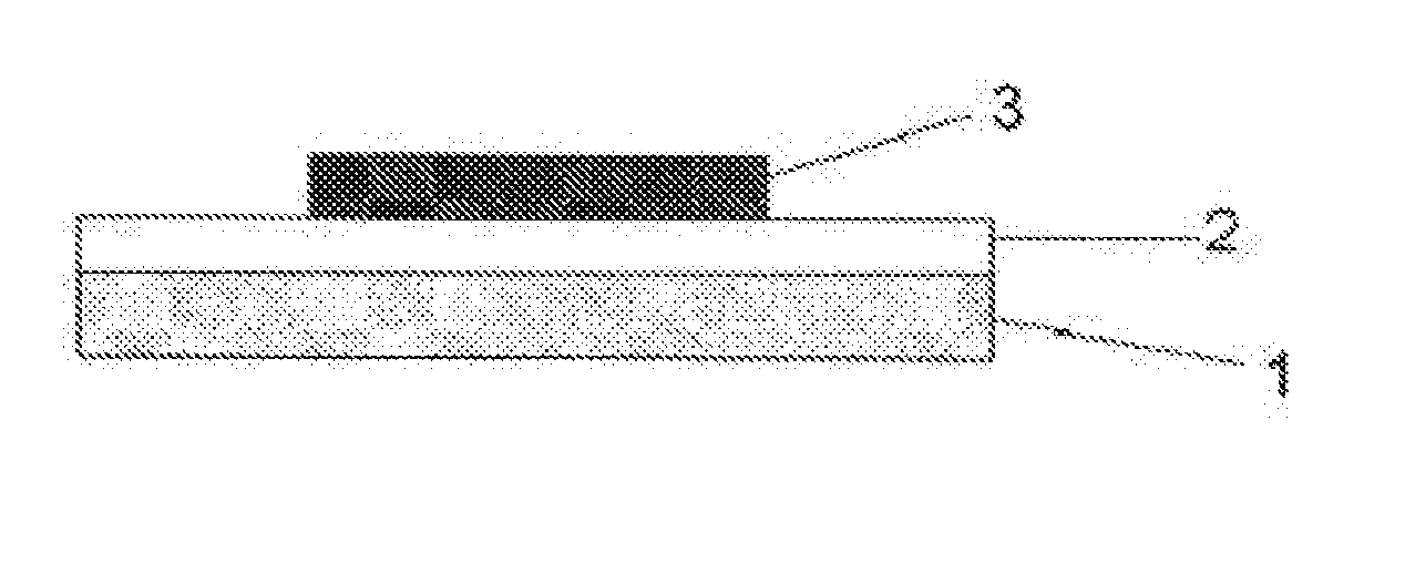
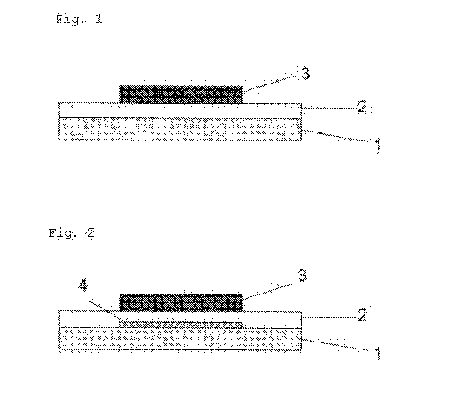
[0116]A white PET film having a thickness of 188 μm (“Crisper K2323” produced by Toyobo Co., Ltd.) was prepared as a base material. A non-color-changing layer having a thickness of 10 μm was formed on the base material using an ink for forming a non-color-changing layer (“Diatone Ecopure SOY HP J” produced by Sakata Inx Corporation).

[0117]Next, a PET film having a thickness of 25 μm (“PET25A PL Shin” produced by Lintec Corporation) was dry-laminated on the non-color-changing layer to form a resin-based transparent cover layer.

[0118]Subsequently, a color-changing layer having a thickness of 5 μm was formed on the transparent cover layer using an ink A for forming a color-changing layer.

[0119]As a result of the above process, an indicator was prepared.

Composition of the Ink a for Forming a Color-Changing Layer

[0120]

TABLE 1Pigment Green 7 (phthalocyanine colorant)8PA-100 (polyamide produced by T&K)7.1Nitrocellulose RS7 (nitrocellulose produced by SNPE3.6Japan)Butyl Cellosolve64.3Aerosi...

example 2

[0121]A white PET film having a thickness of 188 μm (′Crisper K2323″ produced by Toyobo Co., Ltd.) was prepared as a base material. A PET film having a thickness of 25 μm (“PET25A PL Shin” produced by Lintec Corporation) was dry-laminated on the base material to form a resin-based transparent cover layer.

[0122]Next, a color-changing layer having a thickness of 5 μm was formed on the transparent cover layer using an ink B for forming a color-changing layer.

[0123]As a result of the above process, an indicator was prepared.

Composition of the Ink B for Forming a Color-Changing Layer

[0124]

TABLE 2Pigment Yellow 3 (disazo pigment)5Pigment Green 7 (phthalocyanine colorant)7PA-100 (polyamide produced by T&K)7.1Nitrocellulose RS7 (nitrocellulose produced by SNPE3.6Japan)Butyl Cellosolve62.3Aerosil R-972 (silica produced by Nippon Aerosil12Co., Ltd.)Nikkol CA2580 (quaternary ammonium salt surfactant3produced by Nikko Chemicals Co., Ltd.)Total100

example 3

[0125]An indicator was prepared in the same manner as in Example 1, except that the resin-based transparent cover layer was formed using a polyester resin solution (“Sundhoma” produced by DIC Corporation). More specifically, a transparent cover layer having a thickness of 10 μm was formed by repeating silk screen printing six times using the polyester resin solution.


PUM


Abstract

This invention provides a plasma treatment detection indicator that uses a fibrous base material or a synthetic resin base material comprising a coloring pigment as a base material and in which fine fiber pieces or coloring pigment is prevented from being generated in a powder form from the base material in plasma treatment. More specifically, this invention provides a plasma treatment detection indicator comprising a base material and at least a color-changing layer that changes color in a plasma treatment atmosphere, the color-changing layer being disposed above part or all of a surface of the base material, (1) the base material being a fibrous base material or a synthetic resin base material comprising a coloring pigment, and (2) a resin-based or inorganic transparent cover layer that covers all of the surface of the base material being disposed between the base material and the color-changing layer.

Description

TECHNICAL FIELD[0001]The present invention relates to a plasma treatment detection indicator. The plasma treatment as referred to herein means a plasma treatment using plasma generated by applying AC voltage, pulse voltage, high-frequency waves, microwaves, etc., to a gas for generating plasma. The plasma treatment includes both reduced-pressure plasma and atmospheric-pressure plasma.BACKGROUND ART[0002]Various types of equipment, instruments, etc., used in hospitals, laboratories, and the like are sterilized for disinfection and for killing bacteria and fungi. Plasma treatment is known as a sterilization treatment (see, for example, “3.3.1 Teiatsuryoku hoden purazuma wo mochiita mekkin jikken [3.3.1 Sterilization Experiment Using Low-pressure Discharge Plasma]” in Non-patent Literature 1).[0003]Plasma treatment is used not only for sterilization treatment but also for plasma dry etching and plasma cleaning of the surface of items to be treated, such as electronic parts, in the proc...

Claims


Application Information

Patent Timeline
IPC IPC(8): G01N31/22G01D7/00H01J37/32
CPCG01N31/22H01J37/32009H01J2237/334G01D7/005H01J37/3244H01J37/32917H01J37/32935H01J37/32972
Inventor MORI, MARIMO
Owner SAKURA COLOR PRODUCTS CORPORATION
Why Eureka
Try Eureka