Parallel current-sharing device and control method without current-sharing bus

a current-sharing device and control method technology, applied in the field of multi-module parallel current-sharing devices and control methods without current-sharing buses, can solve the problems of increasing the complexity and fault rate of the system, increasing the cost of implementing current-sharing through a current-sharing bus and the complexity of design and production, and the system response becomes slower, etc., to achieve excellent interference suppression capability, simple design, production and debugging of the circuit of the parallel current-sharing devi

Active Publication Date: 2016-12-08
ITECH ELECTRONICS NANJING
View PDF4 Cites 12 Cited by
  • Summary
  • Abstract
  • Description
  • Claims
  • Application Information

AI Technical Summary

Benefits of technology

[0018]In the present invention, an independent current bus and a voltage bus are synthesized into an outer voltage loop control bus, where the control bus is unidirectional and very suitable for differential transmission, so that the system has an excellent interference suppression capability; no inner voltage loop exists in the power conversion submodule, and the voltage control module directly controls the outputs of the power conversion submodules, so that dynamic response of the system is very rapid; the inner current loop in the power conversion submodule forces signals in positive and negative input pins to be equal, to indirectly adjust the output of the outer voltage loop, thereby enabling current sharing of the power conversion submodules; in practice, the bandwidth of the inner current loop may be narrow and the bandwidth of ...

Problems solved by technology

In the current-sharing methods, multiple control loops need to be connected in series, so that the system response becomes slower, especially when multiple power supplies are connected in parallel.
In a scene of serious electromagnetic interference, differential transmission is desired to obtain a high common mode rejection ratio, but two transmitter-receiver sets are required in the differential transmission to enable bidirectional signal transmission, thereby undoubtedly increasing the costs of implementing current sharing through a current bus and the complexity of design and production.
If the foregoing conventional current-sharing control method is adopted, two control buses are required in the system to implement remote voltage compensation and module current equalization, thereby undoubtedly increasing the complexity and fault rate of the system.
Generally, the module current signal is integrated into the cu...

Method used


Image

  • Parallel current-sharing device and control method without current-sharing bus
  • Parallel current-sharing device and control method without current-sharing bus
  • Parallel current-sharing device and control method without current-sharing bus

Examples


Embodiment Construction

[0023]Preferred embodiments of the present invention are described below in detail in combination with the accompanying drawings.

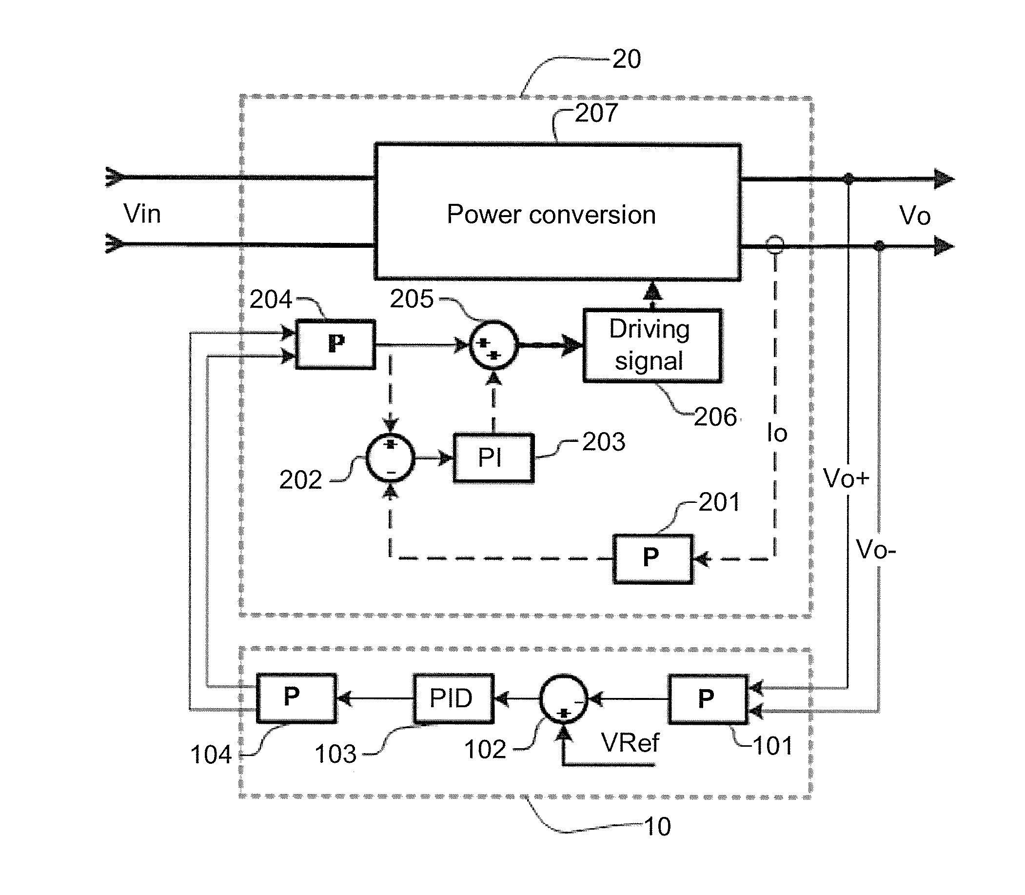
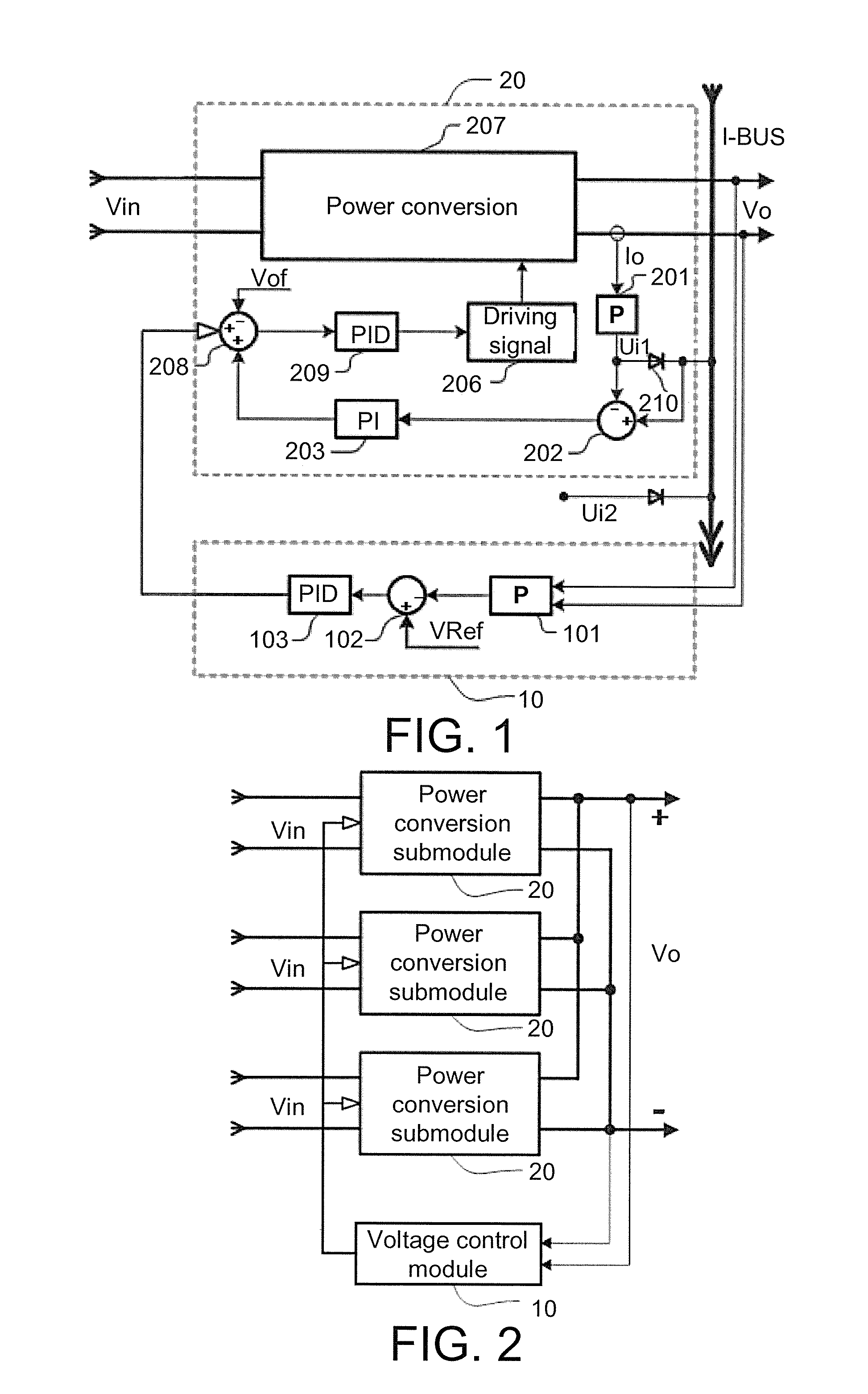
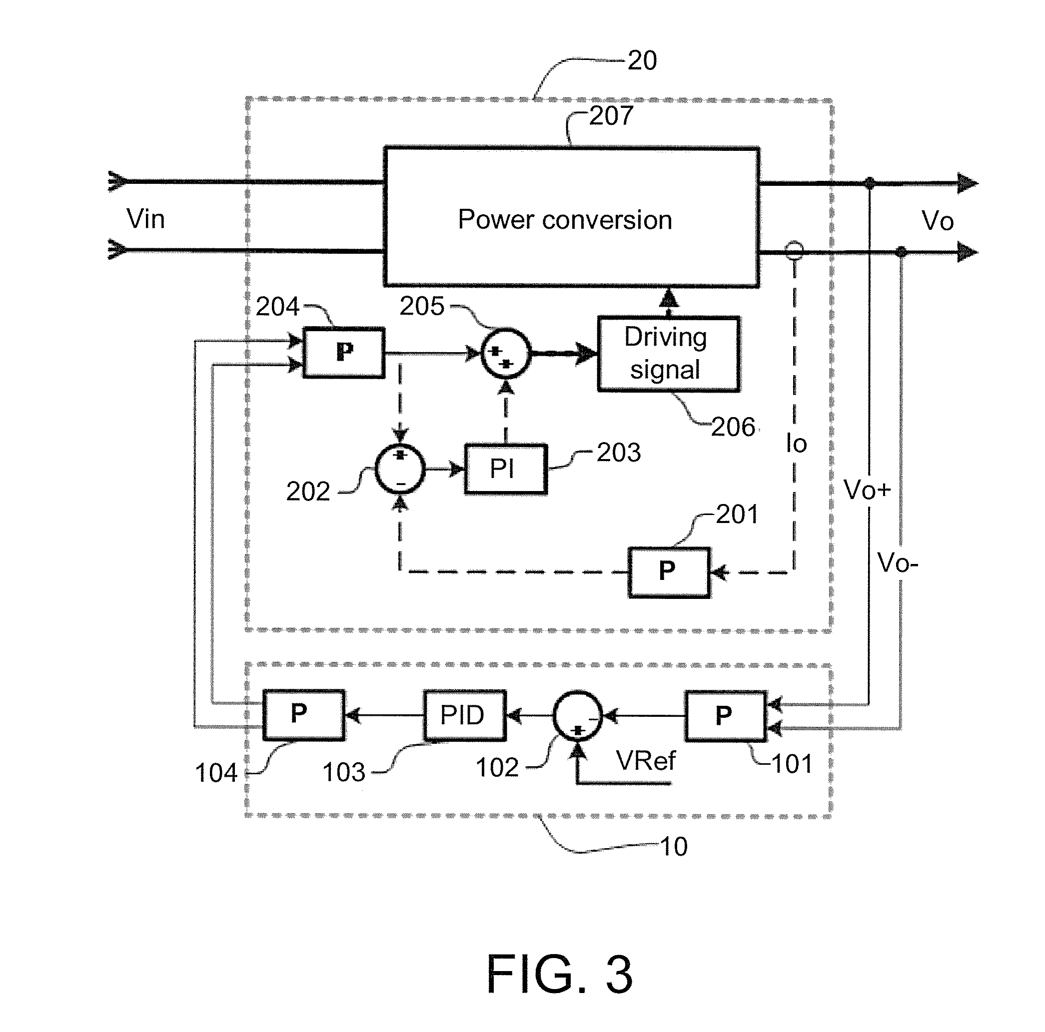
[0024]Embodiment 1: as shown in FIG. 2 and FIG. 3, the present embodiment provides a parallel current-sharing control device without a current-sharing bus, comprising: a voltage control module 10 and three power conversion submodules 20. The voltage control module 10 comprises a first differential amplifier 101, a voltage error amplifier, and a differential driver 104. The voltage error amplifier comprises a voltage subtracter 102 and a PID regulator 103. A terminal voltage signal totally output by the three parallel power conversion submodules is sampled and scaled by the first differential amplifier 101 and then connected to a “−” input end of the voltage subtracter 102 of an outer voltage loop, and a set voltage reference is connected to a “+” input end of the voltage subtracter 102, obtaining an error signal. The error signal is amplified by the PID re...


PUM


Abstract

The present invention provides a parallel current-sharing device and control method without a current-sharing bus, for implementing parallel current sharing of direct-current outputs of a plurality of power conversion submodules. The parallel current-sharing device comprises a voltage control module and a plurality of power conversion submodules. The voltage control module and the plurality of power conversion submodules having parallel outputs form an outer voltage loop. The power conversion submodules comprise respective inner current loops and sample respective current feedback signals to generate inner current loop control signals, and the inner current loop control signals are superposed with an outer voltage loop control signal to control output of the power conversion submodules. An independent current bus is not required, and only one unidirectional outer control voltage loop is required. Functions the same as those of a conventional device are realized; the design, production and debugging of circuits of the parallel current-sharing device are simpler; a rapid multi-parallel dynamic response is realized; a ground wire loop current is eliminated, improving the anti-interference capability of the device; and multi-module parallel current sharing of a switching power supply or a linear power supply under analog control or digital control is realized very easily.

Description

TECHNICAL FIELD[0001]The present invention relates to a power supply control system, and more particularly to a multi-module parallel current-sharing device and control method without a current-sharing bus.BACKGROUND ART[0002]For parallel current-sharing control methods for a conventional high-power switching power supply, such as a master-slave method, a mean value method, and a maximum current method, a maximum current or a mean current is fed back through a current bus, and an error is formed between the maximum current or the mean current and a current in the current bus itself, to adjust a module voltage reference, thereby realizing current sharing, as shown in FIG. 1. In the current-sharing methods, multiple control loops need to be connected in series, so that the system response becomes slower, especially when multiple power supplies are connected in parallel.[0003]In the conventional current-sharing methods, a current bus is required. A module current signal should be integ...

Claims


Application Information

Patent Timeline
IPC IPC(8): G05F1/46H02M3/04
CPCH02M3/04G05F1/46H02M1/009H02M3/1584H02M3/285H02M1/0016H02M1/0025G05F1/56
Inventor MA, HAIBOXING, WEI
Owner ITECH ELECTRONICS NANJING
Why Eureka
Try Eureka