Reactor system for sublimation of pre-clean byproducts and method thereof

Active Publication Date: 2016-12-15
ASM IP HLDG BV
View PDF4 Cites 270 Cited by
  • Summary
  • Abstract
  • Description
  • Claims
  • Application Information

AI Technical Summary

Benefits of technology

[0007]In another aspect, a method may comprise the steps of placing a wafer on a wafer tray inside a reaction chamber assembly; and powering a heating element within the wafer tray to

Problems solved by technology

The presence of an intervening material (e.g., a native oxide layer, such as a silicon oxide material layer on a silicon wafer) on the wafer surface may interfere with formation of a desired material layer over the wafer surf

Method used


Image

  • Reactor system for sublimation of pre-clean byproducts and method thereof
  • Reactor system for sublimation of pre-clean byproducts and method thereof
  • Reactor system for sublimation of pre-clean byproducts and method thereof

Examples


Embodiment Construction

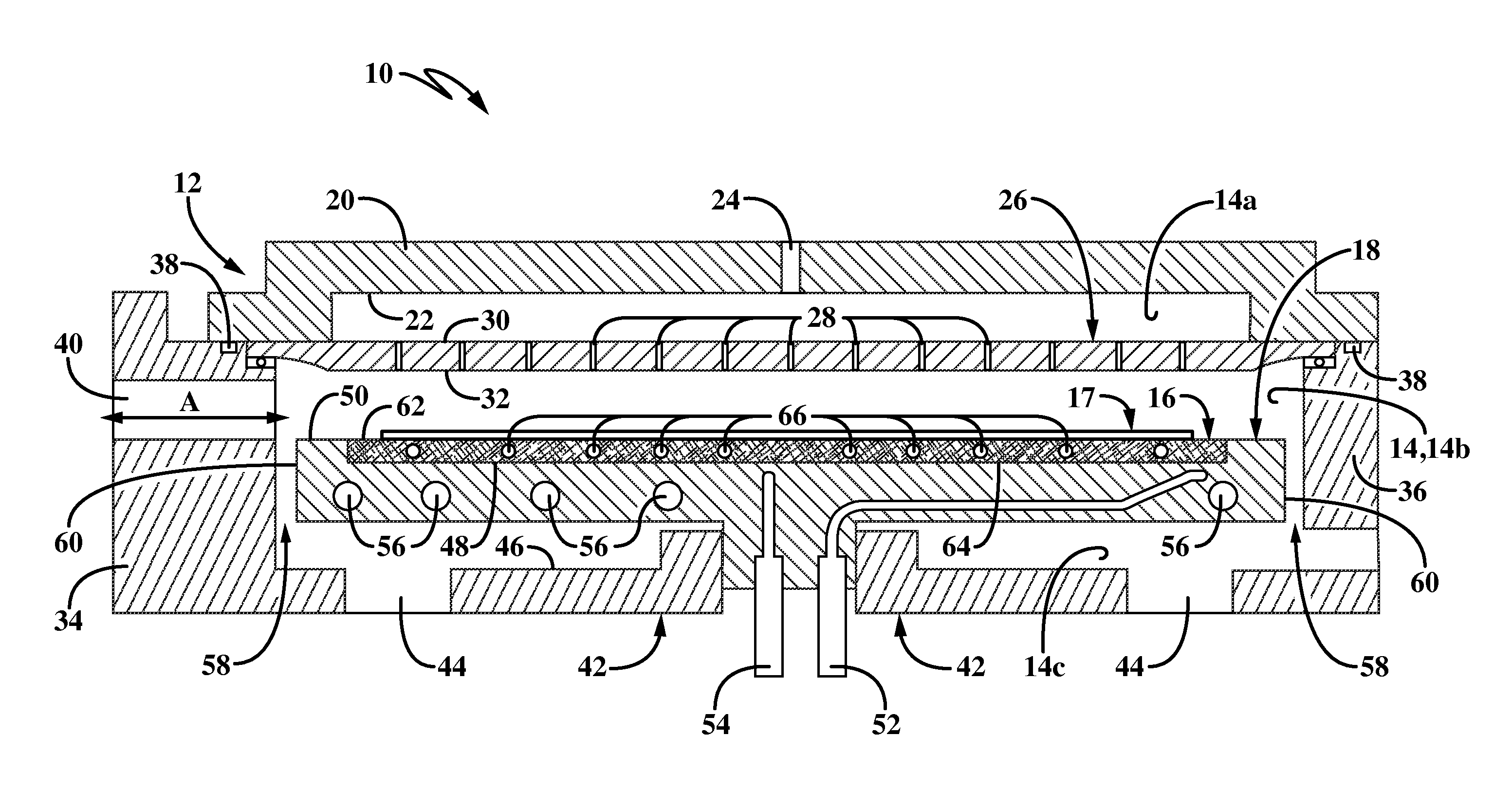
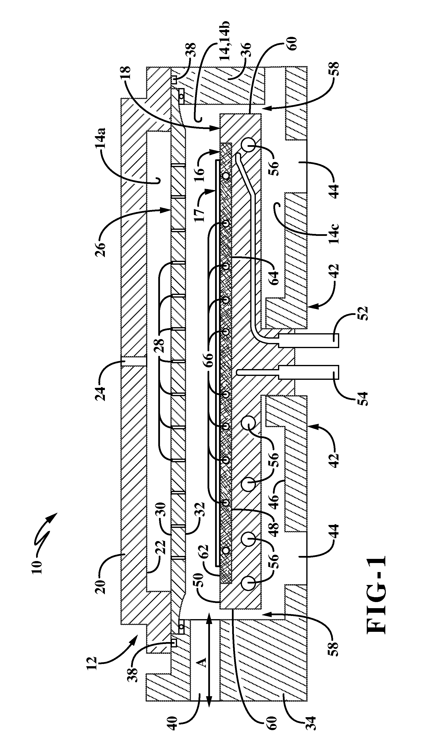
[0013]FIG. 1 shows a reactor system 10 which may include a reaction chamber assembly 34. Assembly 34 which may include a top wall 20, an annular sidewall 36 connected to top wall 20, and a bottom wall 42 connected to sidewall 36. Reactor system 10 / assembly 34 may include a showerhead 12 for directing process gases into an interior reaction chamber 14 defined by assembly 34 and particularly onto a wafer 17 to be processed. Interior chamber 14 may include an upper chamber region or area 14a, a middle or intermediate chamber region or area 14b and a lower chamber area 14c. System 10 may include a wafer tray 16 and a susceptor 18 which are disposed in interior chamber 14. Wafer tray 16 may be seated on or carried by susceptor 18 and may be configured to carry wafer 17 thereon.

[0014]Showerhead 12 may include upper rigid wall or gas channel plate 20, which has an upwardly facing top surface and a downwardly facing bottom surface 22 which may be similarly sized to the top surface. Bottom s...


PUM

PropertyMeasurementUnit
Temperatureaaaaaaaaaa

Abstract

A reactor system and related methods are provided which may include a heating element in a wafer tray. The heating element may be used to heat the wafer tray and a substrate or wafer seated on the wafer tray within a reaction chamber assembly, and may be used to cause sublimation of a native oxide of the wafer.

Description

BACKGROUND[0001]Technical Field[0002]The technical field relates to the fabrication of integrated circuits, particularly to methods and devices for pre-cleaning a wafer or substrate surface.[0003]Background Information[0004]Integrated circuit fabrication often involves formation of one or more material layers on a substrate (also referred to as a “wafer”) surface. These material layers can include, for example, mono-crystalline, polycrystalline, or other amorphous material layers. Formation of the material layers can be achieved using various thin film deposition techniques, including various physical deposition techniques, e.g., physical sputtering, or chemical deposition techniques, e.g. chemical vapor deposition (CVD), atomic layer deposition, or epitaxial deposition. For example, mono-crystalline material formation on a substrate surface can be performed using an epitaxial deposition process, such as for formation of mono-crystalline semiconductor materials (e.g., mon-crystallin...

Claims


Application Information

Patent Timeline
IPC IPC(8): C23C16/44C23C16/458H05B6/10C23C16/46
CPCC23C16/4405H05B6/105C23C16/458C23C16/46C23C14/021C23C14/50C23C16/0209C23C16/0218C23C16/4582H05B3/26H01L21/02041H01L21/324H01L21/67028H01L21/67098H01L21/6773H01L21/683
Inventor TOLLE, JOHNHILL, ERIC
Owner ASM IP HLDG BV
Why Eureka
Try Eureka