Testing of an industrial structure

a technology of industrial structure and test tube, applied in the field of metals, can solve the problems of low number of sensors, lack of reliability of information, and high number of sensors, and achieve the effects of reducing energy consumption, easy interpretation, and strengthening the diffuse nature of the field

Active Publication Date: 2016-12-29
COMMISSARIAT A LENERGIE ATOMIQUE ET AUX ENERGIES ALTERNATIVES
View PDF41 Cites 9 Cited by
  • Summary
  • Abstract
  • Description
  • Claims
  • Application Information

AI Technical Summary

Benefits of technology

[0033]The measurements are performed passively, that is to say without the emission of acoustic waves. Consequently, the energy consumption is reduced and allows for embedded solutions (for example onboard an airplane, a boat or on the seabed).
[0034]The method produces a mapping of the zone to be tested that can easily be interpreted (which limits the risks of false alarms). Th

Problems solved by technology

Concrete technical problems consists for example in detecting and dimensioning a corroded zone on an airplane fuselage.
One general technical problem lies in finding an acceptable trade-off between the number of sensors to be incorporated (cost, bulk, weight, etc.) and the quality of the information that can be recovered by these sensors.
A high number of sensors means a high cost and a low number of sensors often means a lack of reliability of the information, risks of false alarms, or even a lack of redundancy in the event of failure of a sensor.
The multiplication of the sensors however poses other specific problems (for example each incorporated sensor can constitute an additional point of embrittle

Method used


Image

  • Testing of an industrial structure
  • Testing of an industrial structure
  • Testing of an industrial structure

Examples


Embodiment Construction

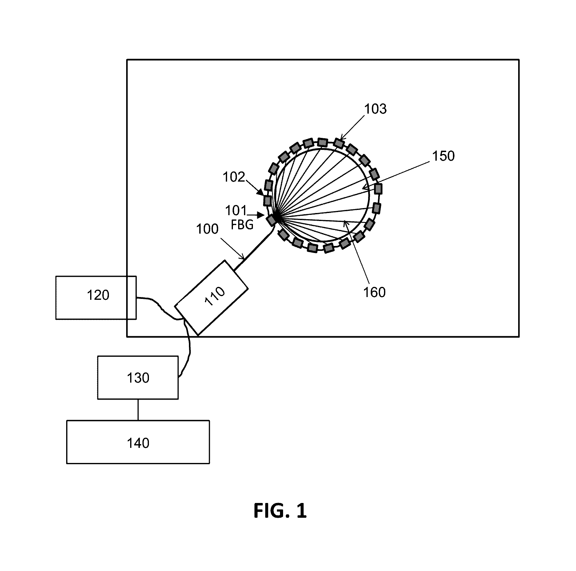
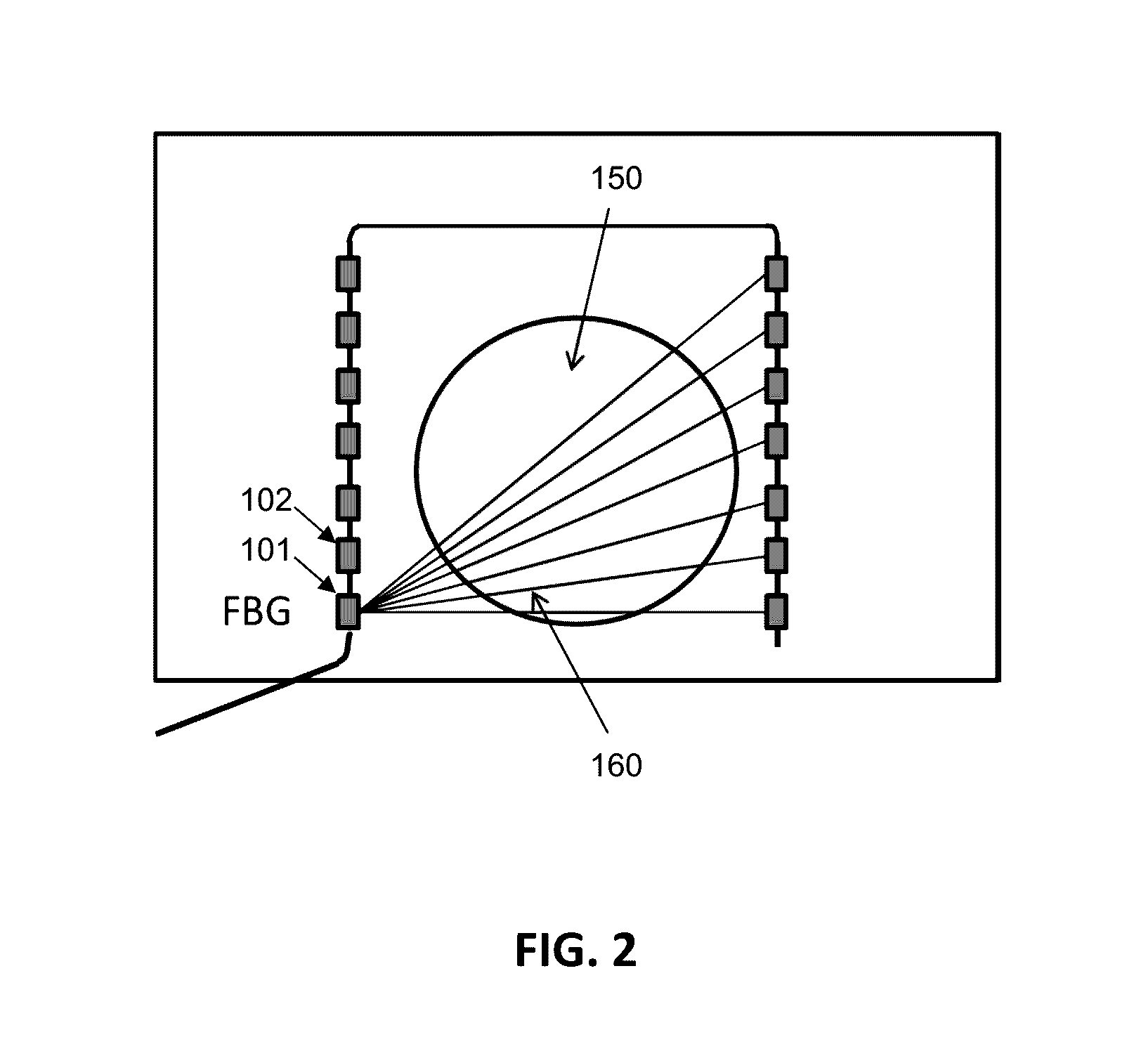
[0046]The invention can advantageously use a large number of measurement points to be able to do the tomography by guided waves. For that, one or more optical fibers on which are etched bragg gratings (FBG) are incorporated in (or glued on) the structure. A single optical fiber can comprise tens of FBGs, and therefore as many measurement points. The bulk is therefore reduced.

[0047]However, the FBGs can operate only as waveguide receiver but not as emitter. The current SHM systems based on FBGs therefore use piezoelectric transducers also as emitter. To do the tomography, there would need to be one piezoelectric transducer for each FBG, therefore still a large number of piezoelectric transducers.

[0048]According to an embodiment of the invention, a technique is described which makes it possible to provide images of structures of industrial type over localized zones and / or of limited thickness (geometry of plate or tube type). The images can notably indicate the velocities of propagati...


PUM


Abstract

A method and a device for analyzing a structure by tomography and diffuse acousto-elastic field correlation are provided. An optical fiber comprising a plurality of measurement points of FBG (Fiber Bragg Grating) type, comprising sensors of Bragg grating type, is deployed in or on the structure to be analyzed. The method comprises the emission of light, into the optical fiber, and the measurement by correlation for each pair of FBG sensors. In a development, a prior imaging of the structure is performed by reconstruction of the velocities of propagation. Other developments comprise: the determination of the positions of the FBG sensors, the calibration of the tomography, the rosette configuration of the sensors forming the measurement points, the use of a plurality of optical fibers, of multiplexers, of lasers, of optical circulators, of omnidirectional optical sensors, of active noise sources, such as piezoelectric transducers, incorporated or not in the structure.

Description

FIELD OF THE INVENTION[0001]The invention relates to the field of metrology and in particular that of checking the health of structures by means of optical fibers.STATE OF THE ART[0002]The checking of the integrity of the structures (works of art, airplanes or pipe-lines for example) during their life is done generally during maintenance operations, with human inspection and intervention. Concrete technical problems consists for example in detecting and dimensioning a corroded zone on an airplane fuselage.[0003]For these integrity checks, so-called non-destructive testing (NDT) methods are generally used, by so-called “conventional” methods (ultrasound, electromagnetic methods, etc.).[0004]For a number of years now there have been research developments aiming to incorporate sensors in the structure at key points of the structures, and do so in order to automate the measurements (for example at regular intervals, these intervals being generally close together in time) and to be able ...

Claims


Application Information

Patent Timeline
IPC IPC(8): G01N21/17G01M5/00G01N29/24G01D5/353G01N29/06G01N29/07
CPCG01N21/1702G01N29/0672G01N29/07G01N29/2418G01D5/35316G01N2201/1211G01M5/0025G01N2291/011G01N2291/2694G01N2021/1706G01N2201/088G01M5/0016G01M5/0008G01M5/0091G01M11/085
Inventor CHAPUIS, BASTIEN
Owner COMMISSARIAT A LENERGIE ATOMIQUE ET AUX ENERGIES ALTERNATIVES
Why Eureka
Try Eureka