A cvi densification installation including a high capacity preheating zone

a technology of densification installation and preheating zone, which is applied in the direction of lighting and heating apparatus, heat treatment, chemical vapor deposition coating, etc., can solve the problems of increasing the complexity and the overall size of the installation, difficult to control the temperature of the reactive gas in the preheater chamber, and the infiltration process of chemical vapor requires expensive investments, so as to increase the volume and enhance the productivity of the installation

Active Publication Date: 2017-01-05
SAFRAN CERAMICS SA
View PDF10 Cites 12 Cited by
  • Summary
  • Abstract
  • Description
  • Claims
  • Application Information

AI Technical Summary

Benefits of technology

[0010]An object of the invention is to propose a design for a thermochemical treatment installation that enables a gas stream to be preheated to a determined temperature while minimizing temperature differen...

Problems solved by technology

Such preheater means increase the complexity and the overall size of the installation.
Nevertheless, although the preheater chamber enables the reactive gas to be heated prior to being introduced into the loading zone, it is difficult to control the temperature of the reactive...

Method used


Image

  • A cvi densification installation including a high capacity preheating zone
  • A cvi densification installation including a high capacity preheating zone
  • A cvi densification installation including a high capacity preheating zone

Examples


Embodiment Construction

[0024]The invention applies to any type of installation or oven used for performing heat treatment and in which the gas used in the treatment is preheated in a preheater chamber prior to being introduced into the treatment or loading zone of the installation. Such installations are used in particular for performing thermochemical treatments such as carburizing parts or densifying porous substrates by chemical vapor infiltration.

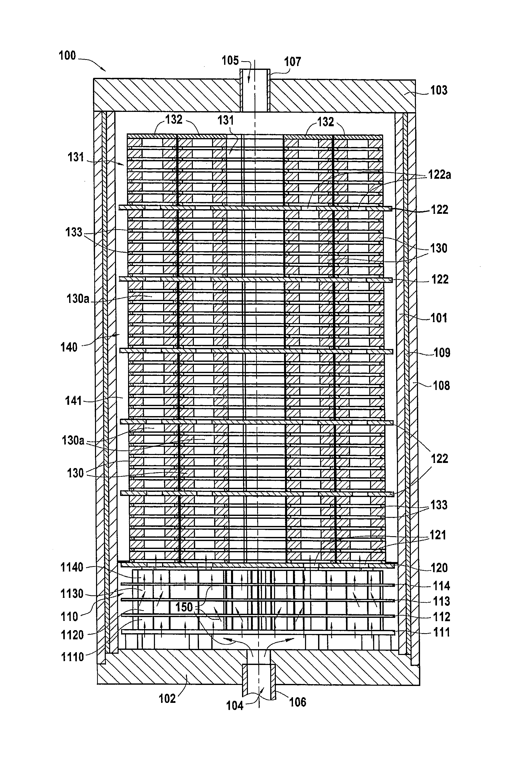
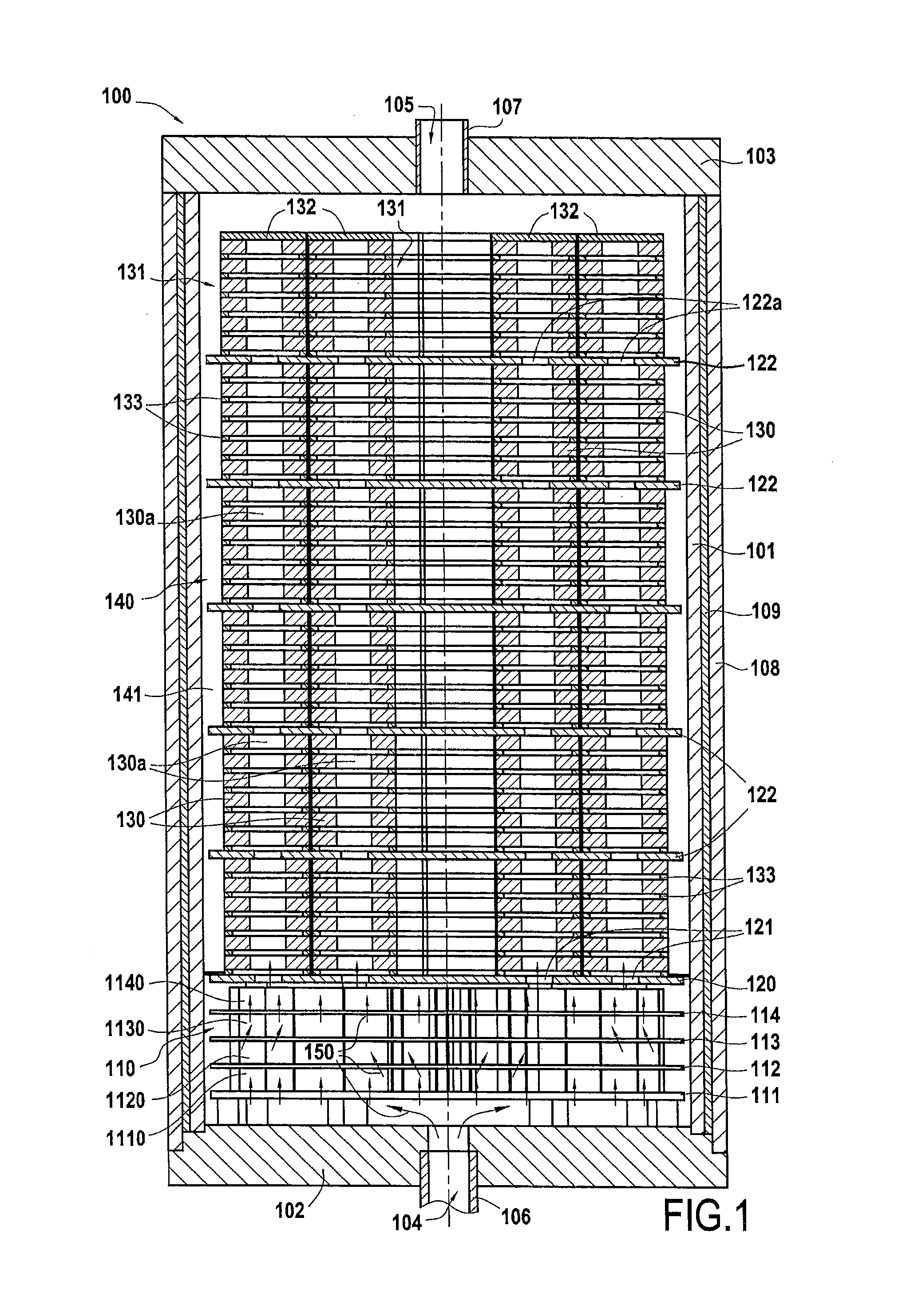
[0025]A first embodiment of a densification oven is described with reference to FIGS. 1 to 3. FIG. 1 is a diagram showing an installation 100 for densification by chemical vapor infiltration that is defined by a cylindrical side wall 101, a bottom wall 102, and a top wall 103.

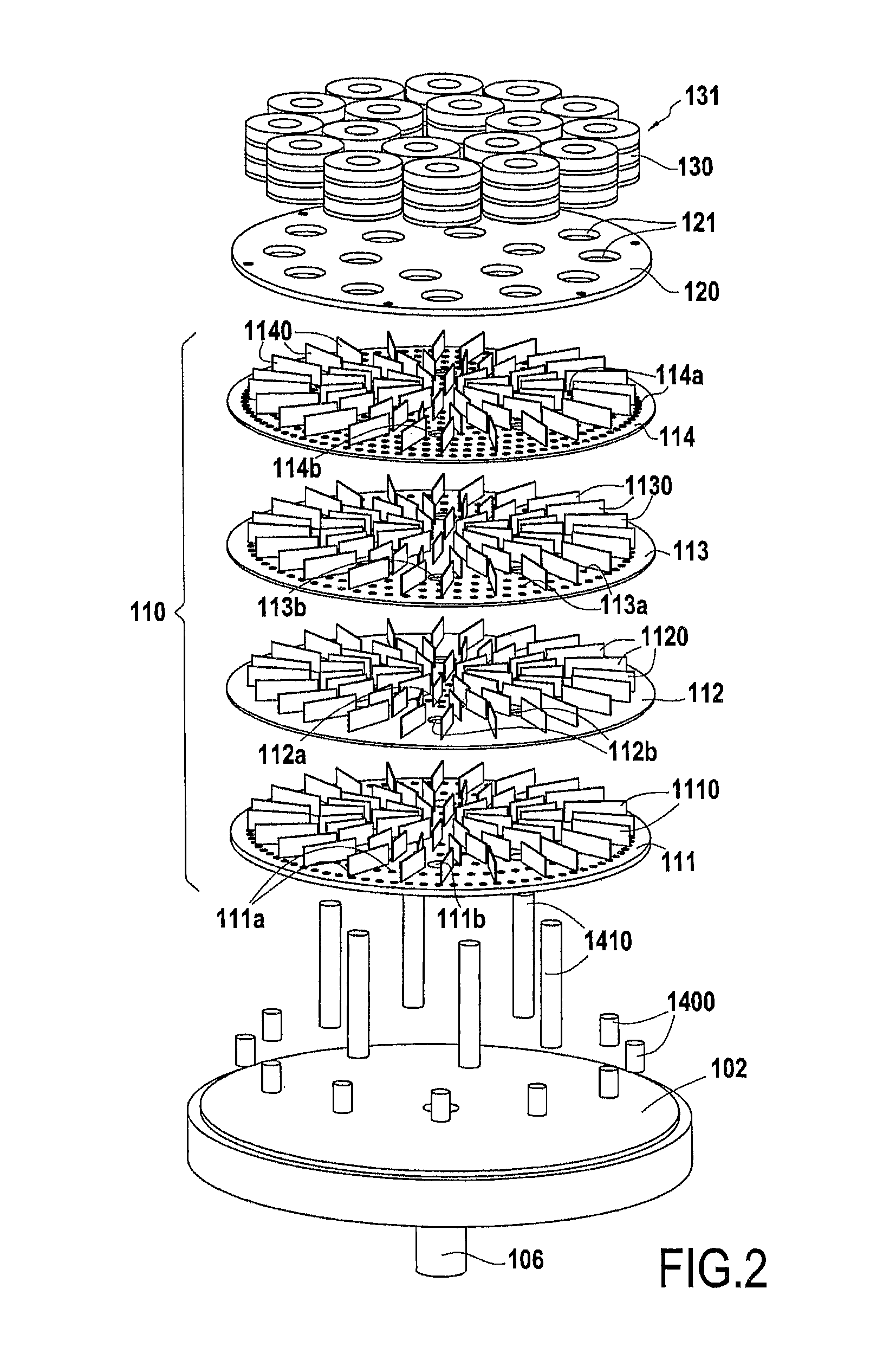
[0026]A gas preheater chamber 110, of structure that is described in detail below, extends between the bottom 102 of the oven and a loading tray 120. A pipe 106 connects the reactive gas inlet 104 to the preheater chamber 110 through the bottom 102.

[0027]Substrates 130 for densifying are...


PUM

PropertyMeasurementUnit
Shapeaaaaaaaaaa
Thermal conductivityaaaaaaaaaa

Abstract

A thermochemical treatment installation includes a reaction chamber, at least one gas inlet, and a gas preheater chamber situated between the gas inlet and the reaction chamber. The preheater chamber has a plurality of perforated distribution trays held spaced apart one above another. The preheater chamber also includes, between at least the facing distribution trays, a plurality of walls defining flow paths for a gas stream between said trays.

Description

BACKGROUND OF THE INVENTION[0001]The invention relates to installations or ovens used for performing heat treatment, and in which the gas used in the treatment is preheated prior to being introduced into the treatment chamber of the installation. Such installations are used in particular for performing thermochemical treatments, such as carburizing parts or densifying porous substrates by chemical vapor infiltration.[0002]A field of application of the invention is that of making parts out of thermostructural composite material, i.e. out of composite material that possesses both mechanical properties that make it suitable for constituting structural parts and also the ability to conserve those properties up to high temperatures. Typical examples of thermostructural composite materials are carbon / carbon (C / C) composites have a reinforcing fabric of carbon fibers densified by a matrix of pyrolytic carbon, and ceramic matrix composites (CMC) having a reinforcing fabric of refractory fib...

Claims


Application Information

Patent Timeline
IPC IPC(8): C23C16/46B01J6/00B01J8/02C23C16/455F28F13/06F27B5/16F27D7/06F27D99/00F28F3/08C04B35/80C23C16/458
CPCC23C16/455C23C16/045C23C16/452C23C16/45591F27B5/16F28F3/086F28F13/06F27D7/06F27D99/0001C04B2235/5268B01J6/00B01J8/0285B01J2208/00407B01J2208/00415B01J2208/00469B01J2208/00884B01J2208/00938B01J2219/00006C04B35/80F28C3/005F28D2021/0022C04B35/83C04B2235/614C04B35/56C23C8/20F28F3/08C23C16/04B01J2208/00433C04B2235/425C23C16/4557C23C16/4583C23C16/46
Inventor DELPERIER, BERNARDPOTIN, JEAN-FRANCOISSOULIGNAC, SOPHIE
Owner SAFRAN CERAMICS SA
Why Eureka
Try Eureka