Hybrid bonded turbine rotors and methods for manufacturing the same

Active Publication Date: 2017-01-26
HONEYWELL INT INC
View PDF1 Cites 43 Cited by
  • Summary
  • Abstract
  • Description
  • Claims
  • Application Information

AI Technical Summary

Benefits of technology

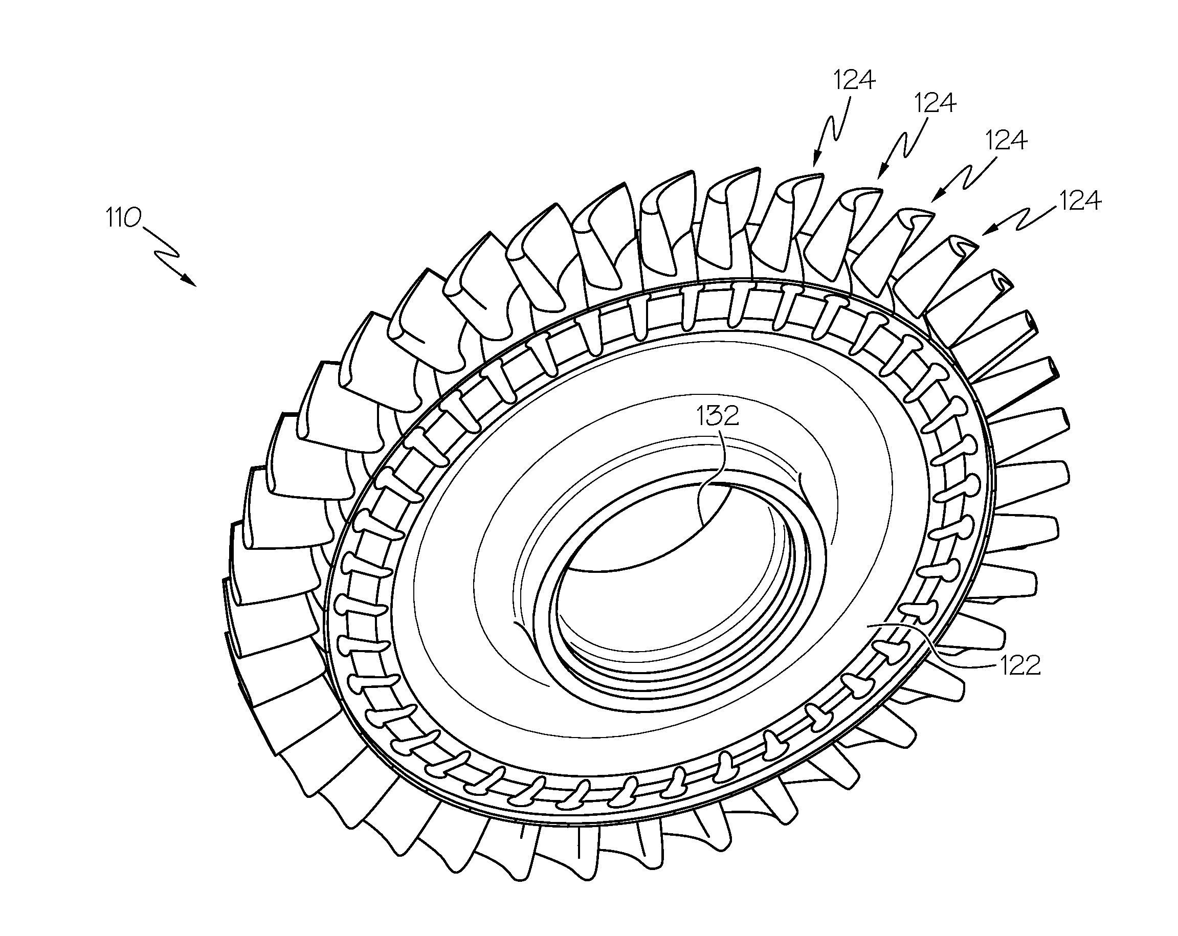
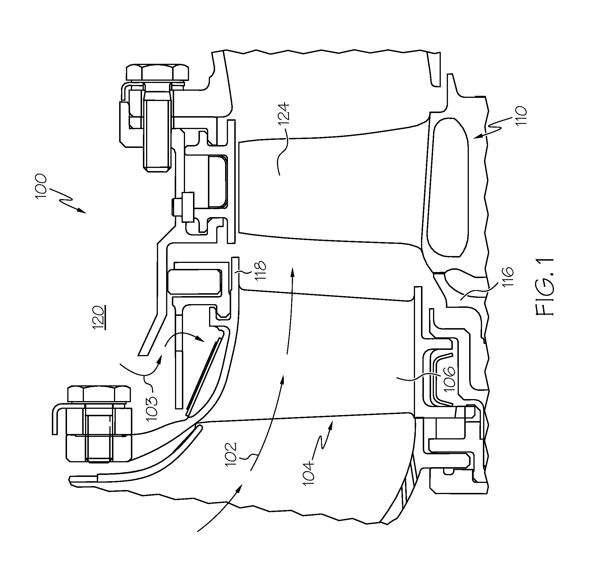
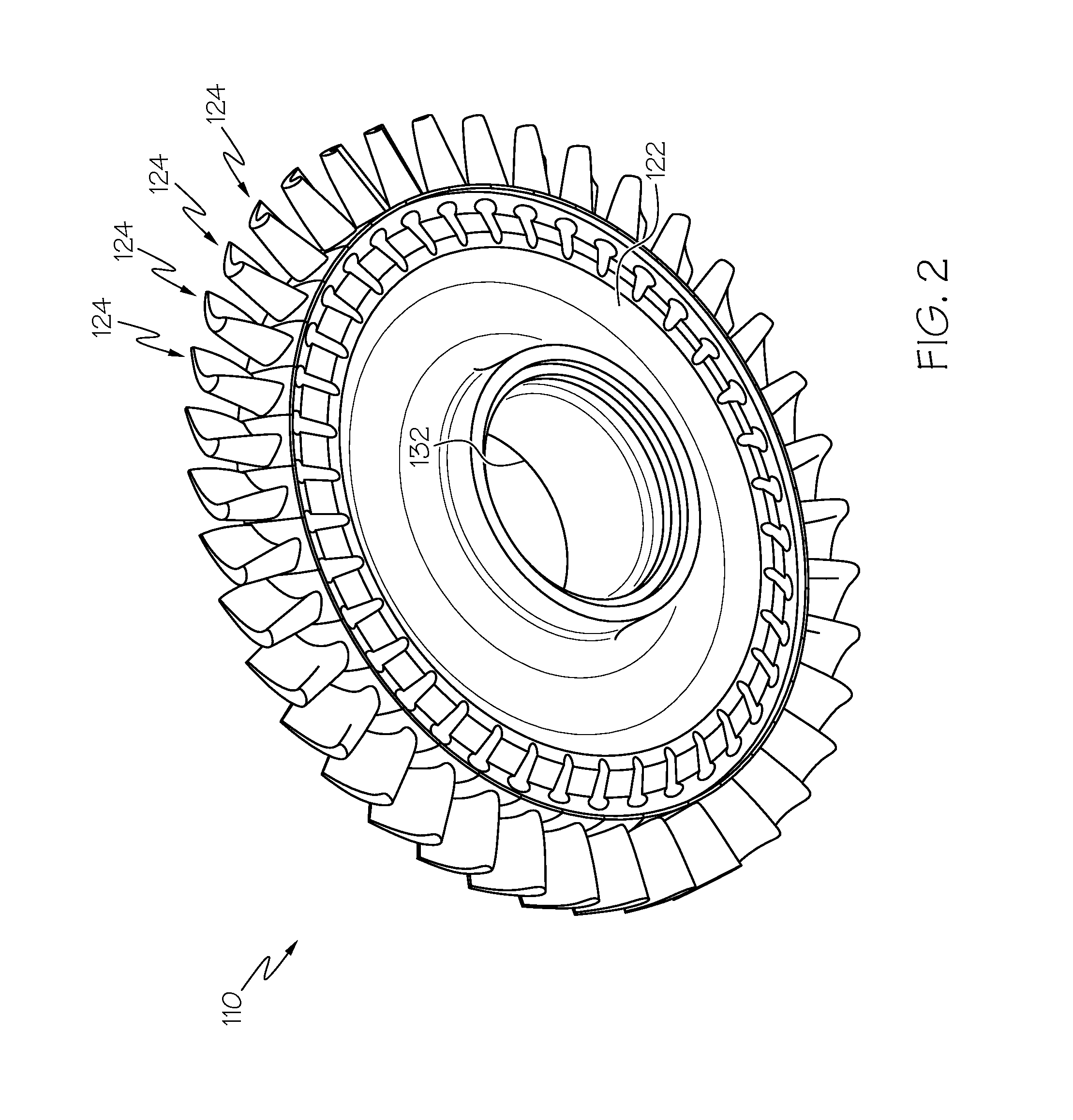
[0042]The term “bond plane” includes a planar bond plane, a curved bond plane, or a conical bond plane. The metallurgical bonds in the hybrid bonded turbine rotor 110 form the continuous bond plane 126 (FIGS. 6A and 6B) that is above the live rim 130 of the turbine disk. As noted previously, the radial position of the bond plane is determined in step 20 based on thermal and stress optimizations to achieve maximum strength and life for the hybrid bonded turbine rotor. The selected radial position of the bond plane outboard of the live rim depends upon the stress and temperature in the area proximate the bond plane and the physical requirement that the base of the shank portion of the turbine blade is contoured to the outer surface (rim) of the turbine disk. The step of linear friction welding each turbine blade to the turbine disk is repeated until the plurality of turbine blades provided in step 40 are metallurgically bonded to the turbine disk (more particularly, to the corresponding raised blade attachments surfaces 140 thereof) at which point the entire linear friction welding operation is complete, thereby forming a “bonded assembly”. The bond plane in the bonded assembly may be larger than contact bearing areas of conventional insertable blade turbine rotors. A larger bond plane area enables higher rotational speeds, increased cycle efficiency, and decreased specific fuel consumption. The bonded assembly includes the shank cavity 128 (e.g., FIG. 6A) between each pair of adjacent turbine blades (more particularly between shank portions of adjacent turbine blades as hereinafter described). The shank cavities reduce turbine rotor weight and turbine rotor inertia. The shank cavities 128 may be refined in a subsequent machining step as hereinafter described.
[0043]In general, as known to one skilled in the art, linear friction welding (LFW) is a solid state joining process in which a stationary part (here, the turbine disk) is forced against a part (here, the turbine blade) that is reciprocating in a linear manner in order to generate frictional heat. The reciprocating motion may be along any direction that does not interfere with adjacent blades. The direction of reciprocating motion may be generally parallel to the platform angle, which is substantially parallel with the platform tangential edges (that extend outward

Problems solved by technology

Increased temperatures at the turbine disk rim and stress/temperature combinations well above the metallurgical limit of the conventional turbine rotor result, limiting turbine rotor life and hindering engine cycle improvement options.
For example, a conventional turbine rotor using an insertable fir-tree design for attaching the turbine blades of a single crystal (SC) alloy to the turbine disk of a powder metal (PM) alloy may not be strong enough to sustain high speed stresses at the higher T3 and T4.1 temperatures, and the turbine disk may not be capable of attaining adequate life at rim temperatures above 1,300 to 1,400° F. In addition, such conventional turbine rotors are expensive to manufacture, susceptible to detachment or separation of the turbine disk due to high stress/temperature combinations, and there is a potential for turbine blade walking (axial dislocation of the turbine blade in the disk).
There are inherent metallurgical problems with brazing or diffusion bonding the SC turbine blades to the PM turbine disk as these bonding techniques are performed at high temperatures and may compromise the microstructure of the turbine disk.
In addition, the multiple high temperature thermal cycles from bonding and heat treatment will

Method used


Image

  • Hybrid bonded turbine rotors and methods for manufacturing the same
  • Hybrid bonded turbine rotors and methods for manufacturing the same
  • Hybrid bonded turbine rotors and methods for manufacturing the same

Examples


Embodiment Construction

[0023]The following detailed description is merely exemplary in nature and is not intended to limit the invention or the application and uses of the invention. As used herein, the word “exemplary” means “serving as an example, instance, or illustration.” Thus, any embodiment described herein as “exemplary” is not necessarily to be construed as preferred or advantageous over other embodiments. All of the embodiments described herein are exemplary embodiments provided to enable persons skilled in the art to make or use the invention and not to limit the scope of the invention which is defined by the claims. Furthermore, there is no intention to be bound by any expressed or implied theory presented in the preceding technical field, background, brief summary, or the following detailed description.

[0024]Various embodiments are directed to hybrid bonded turbine rotors and methods for manufacturing the same. In particular, this invention makes use of one or more “compliant” alloy material ...


PUM


Abstract

Hybrid bonded turbine rotors and methods for manufacturing the same are provided. A method for manufacturing a hybrid bonded turbine rotor comprises the steps of providing turbine disk having a rim portion comprising a live rim of circumferentially continuous material and a plurality of live rim notches in an outer periphery of the turbine disk alternating with a plurality of raised blade attachment surfaces defining the outer periphery; providing a plurality of turbine blades, each of which comprising an airfoil portion and a shank portion, the shank portion having a base surface; metallurgically bonding a compliant alloy material layer to either or both of the raised blade attachments surfaces of the turbine disk and the base surfaces of the blade shanks; and linear friction welding the plurality of blades to the turbine disk so as to form a bond plane between the raised blade attachments surfaces of the turbine disk and the base surfaces of the blade shanks, the compliant alloy material layer being disposed at the bond plane.

Description

TECHNICAL FIELD[0001]The present invention generally relates to gas turbine engines, and more particularly relates to hybrid bonded turbine rotors and methods for manufacturing the same.BACKGROUND[0002]Gas turbine engines may be used to power various types of vehicles and systems, such as air or land-based vehicles. In typical gas turbine engines, compressed air generated by axial and / or radial compressors is mixed with fuel and burned, and the expanding hot combustion gases are directed along a flowpath and through a turbine nozzle having stationary vanes. The combustion gas flow deflects off of the vanes and impinges upon turbine blades of a turbine rotor. A rotatable turbine disk or wheel, from which the turbine blades extend, spins at high speeds to produce power. Gas turbine engines used in aircraft use the power to draw more air into the engine and to pass high velocity combustion gas out of the gas turbine aft end to produce a forward thrust. Other gas turbine engines may use...

Claims


Application Information

Patent Timeline
IPC IPC(8): F01D5/30B23K20/12B23K20/22B23K20/02B23K20/14B23K20/08B23K9/167B23K9/23B23K5/14B23K5/00B23K10/02B23K15/00B23K26/32B23K26/21F01D5/02
CPCF01D5/3061B23K2203/08B23K20/1205B23K20/22B23K20/023B23K20/14B23K20/08B23K20/02B23K9/167B23K9/23B23K5/14B23K5/003B23K10/02B23K15/0093B23K15/0046B23K26/32B23K26/21F05D2220/32F05D2230/235F05D2230/233F05D2230/234F05D2230/236F05D2230/239F05D2230/42F05D2300/175F05D2300/177F01D5/02B23K20/16B23K2101/001F01D5/082F01D5/34F01D11/006F05D2300/606F05D2300/607Y02T50/60
Inventor WALDMAN, DAVID R.MITTENDORF, DONMORRIS, MARK C.VINUP, MICHAEL
Owner HONEYWELL INT INC
Why Eureka
Try Eureka