
Surface wave polarization converter

a polarization converter and surface wave technology, applied in the direction of antenna earthing, basic electric elements, antennas, etc., can solve the problems of no reference, no disclosure of polarization conversion, no suggestion or disclosure of a way to convert incident waves, etc., to achieve the effect of reducing (or increasing) coupling

Active Publication Date: 2017-01-26
HRL LAB
View PDF0 Cites 16 Cited by
  • Summary
  • Abstract
  • Description
  • Claims
  • Application Information

AI Technical Summary

Benefits of technology

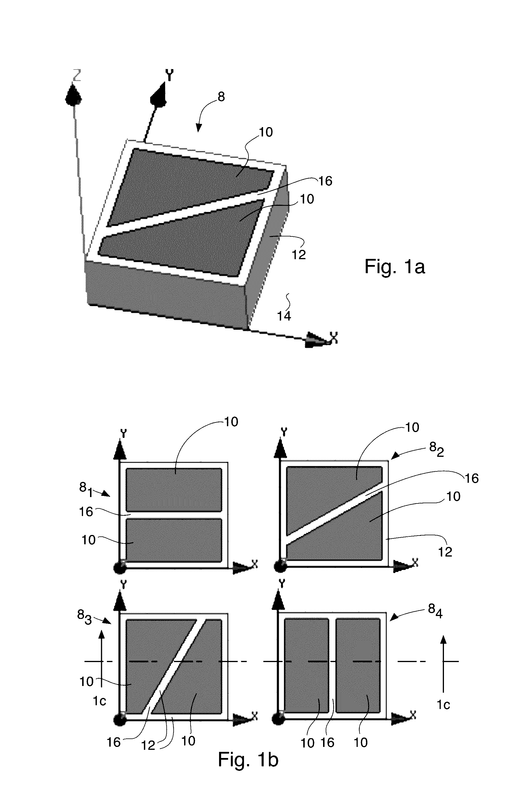
The present invention allows a designer to switch between polarizations within a single design and alter the coupling between antennas or objects on a surface. It provides an apparatus for converting surface bound electro-magnetic waves from one linear combination of surface bound electromagnetic modes to a different linear combination of surface bound electromagnetic modes, and also allows for the conversion of electro-magnetic surface waves from TE mode to TM mode or from TM mode to TE mode. The invention also provides a method of converting a surface bound electromagnetic wave from a first surface bound mode to a second surface bound mode by arranging a plurality of unit cells in an array of cells, with the orientation of a linear slice or gap in the unit cells changing from cell to cell as the surface bound electromagnetic wave moves through the cells.

Problems solved by technology

A typical challenge for such designers has been the integration of antennas onto complex metallic shapes while retaining the desired radiation characteristics.
However, no reference is made to polarization and no disclosure of polarization conversion is disclosed.
While TM and TE modes are discussed, this prior art does not suggest or disclose a way to convert polarizations of an incident wave.
However, this prior art does not disclose a structure or method to convert the polarization of surface waves between pure TE and TM polarizations.
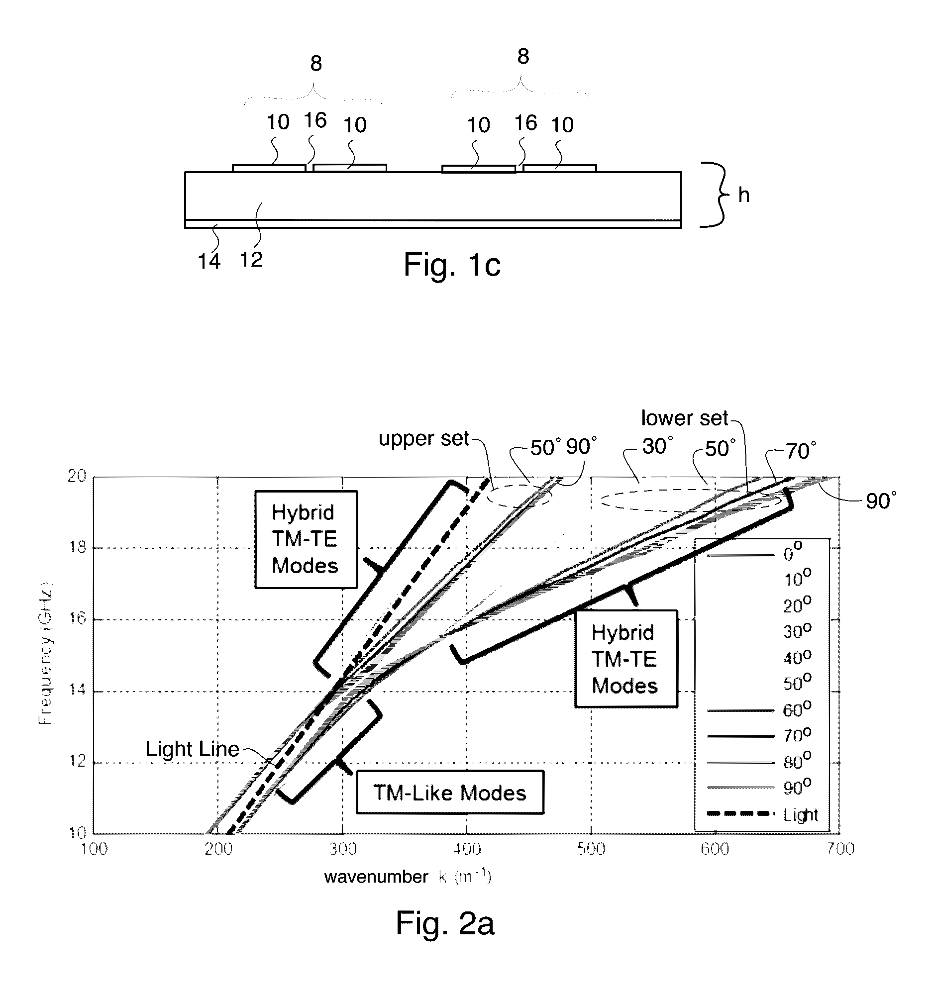
Hybrid TM-TE modes are not correctly modeled by a single tensor impedance boundary.

Method used


Image

  • Surface wave polarization converter
  • Surface wave polarization converter
  • Surface wave polarization converter

Examples


Embodiment Construction

[0035]In the following description, numerous specific details are set forth to clearly describe various specific embodiments disclosed herein. One skilled in the art, however, will understand that the presently claimed invention may be practiced without all of the specific details discussed below. In other instances, well known features have not been described so as not to obscure the invention.

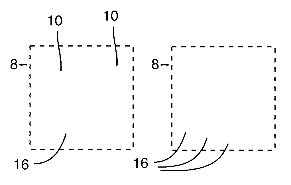
[0036]The present invention discloses an electromagnetic transport medium or surface which can convert the polarization of surface bound waves between pure TE and TM polarizations, for example. The electromagnetic transport medium or surface is created by patterning metallic patches or plates 10 disposed on one major surface of a dielectric substrate 12. In the preferred embodiments, the dielectric substrate has a ground plane 14 disposed on its other (opposing) major surface.

[0037]The patches or plates 10 preferably utilize a sliced unit cell arrangement that was first presented in “Scalar a...


PUM


Abstract

A method and apparatus for converting electromagnetic surface waves from TE mode to TM mode or from TM mode to TE mode. The apparatus includes a dielectric surface having an anisotropic impedance tensor which is preferably obtained by a plurality of electrically conductive unit cells disposed on the dielectric surface and arranged in a two dimensional array of unit cells, a majority of the unit cells in said array being divided into at least two portions, with at least one gap separating the at least two portions from each other into two or more patches or plates, the array of unit cells having a surface wave input end and a surface wave output end, gaps in the unit cells disposed closest to the surface wave input end having a first orientation and gaps in said unit cells disposed closest to the surface wave output end having a second orientation different than said first orientation. The electromagnetic surface waves have a frequency greater than a TE cutoff frequency determined by a second solution of Maxwell's equations for said dielectric surface.

Description

CROSS REFERENCE TO RELATED APPLICATIONS[0001]This application claims the benefit of U.S. Provisional Patent Application No. 62 / 194,743 filed Jul. 20, 2015, the disclosure of which is hereby incorporated herein by reference.STATEMENT REGARDING FEDERALLY SPONSORED RESEARCH OR DEVELOPMENT[0002]NoneTECHNICAL FIELD[0003]The invention relates to devices for converting electromagnetic surface waves between the two fundamental polarizations: transverse magnetic (TM) and transverse electric (TE). TM modes have an electric field polarized in the propagating direction and normal to the surface, and magnetic field in the transverse direction. TE modes conversely have magnetic field in the propagating direction and normal directions and electric field in the transverse direction. The invention employs an impedance surface, created by patterning metallic patches on a grounded dielectric substrate, to convert the polarization of surface waves between TE and TM polarizations.BACKGROUND[0004]Artific...

Claims


Application Information

Patent Timeline
IPC IPC(8): H01Q15/24H01Q9/04H01Q1/36H01Q1/48
CPCH01Q15/246H01Q1/36H01Q9/0407H01Q1/48H01Q21/065H01P1/165H01Q15/0086
Inventor QUARFOTH, RYAN G.PATEL, AMIT M.
Owner HRL LAB
Learn More