Single stage isolated ac/dc power factor corrected converter

a converter and power factor technology, applied in the direction of electric variable regulation, process and machine control, instruments, etc., can solve the problems of large overvoltage of voltage across switch sb>1/b>, increase in cost, and difficulty in achieving short circuit current limiting, etc., to achieve the effect of improving the efficiency of the converter

Active Publication Date: 2017-01-26
DAVIDSON CHRISTOPHER DONOVAN
View PDF9 Cites 52 Cited by
  • Summary
  • Abstract
  • Description
  • Claims
  • Application Information

AI Technical Summary

Benefits of technology

[0019]An addition to the second aspect of the invention is a flipping circuit consisting of a series combination of a bidirectional switch and an inductor connected in parallel with the clamp capacitor to flip the polarity of the voltage on clamp capacitor at the zero voltage crossing time of the AC input. The bi-directional switch can be realized with back to back MOSFETs, or back to back IGBTs with anti-parallel diodes or by anti-parallel SCRs with diodes connected in series or by a Triac. This circuit relieves the rest of the primary circuitry form the burden of flipping the polarity of the voltage on clamp capacitor thus improving the efficiency of the converter. The converter still has to flip the voltage across the output DC blocking capacitor after the zero cross time but it turns out it can do this quite easily without an additional circuit.

Problems solved by technology

This approach has been shown to be effective and efficient in both low power and higher power applications but involves several conversion stages which increases the cost.
However overload and short circuit current limiting is difficult to achieve and a second winding in the inductor is required to absorb the input inductor energy should both switching devices be turned off at the same time, which impresses extra voltage on the switching devices.
One problem introduced by the resonant inductor Lr when it is connected effectively in series with the current path when S1 is off (and by the transformer leakage inductance) is that the voltage across switch S1 will have a large overvoltage due to the inductor L driving current into these smaller inductances.
Accordingly this converter suffers from high losses as the energy stored in the resonant inductance is not recovered.
This version is not a true bridgeless PFC converter. S. Nigsch et al. in “Analysis, Modelling and Design of a True Bridgeless Single Stage PFC with Galvanic Isolation”, APEC2015, Charlotte N.C., March 2015 proposes using an inferior and complicated clamp circuit with two MOSFETs with series connected diodes which is difficult to control and does not allow Zero Voltage Switching.

Method used


Image

  • Single stage isolated ac/dc power factor corrected converter
  • Single stage isolated ac/dc power factor corrected converter
  • Single stage isolated ac/dc power factor corrected converter

Examples


Embodiment Construction

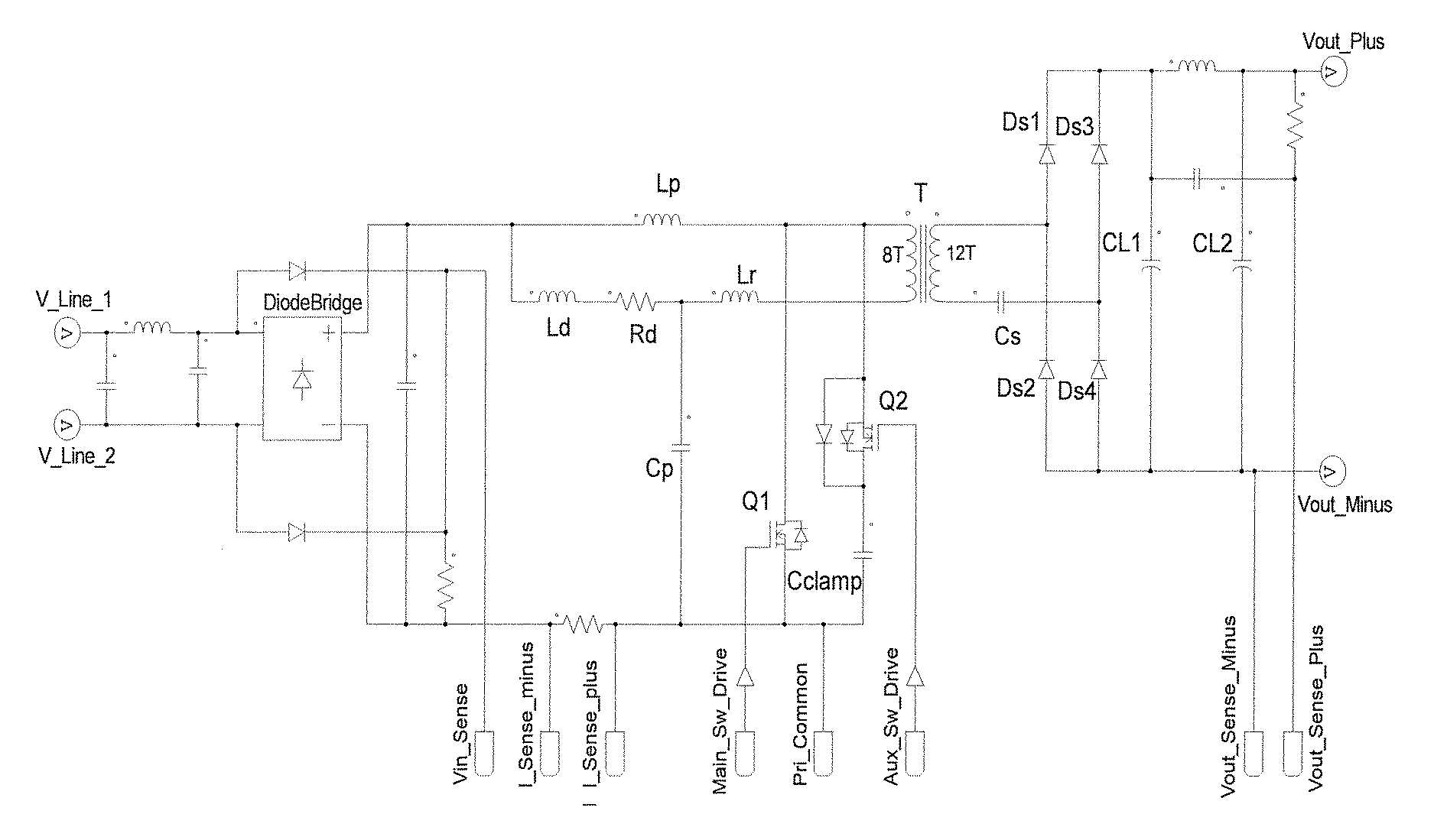
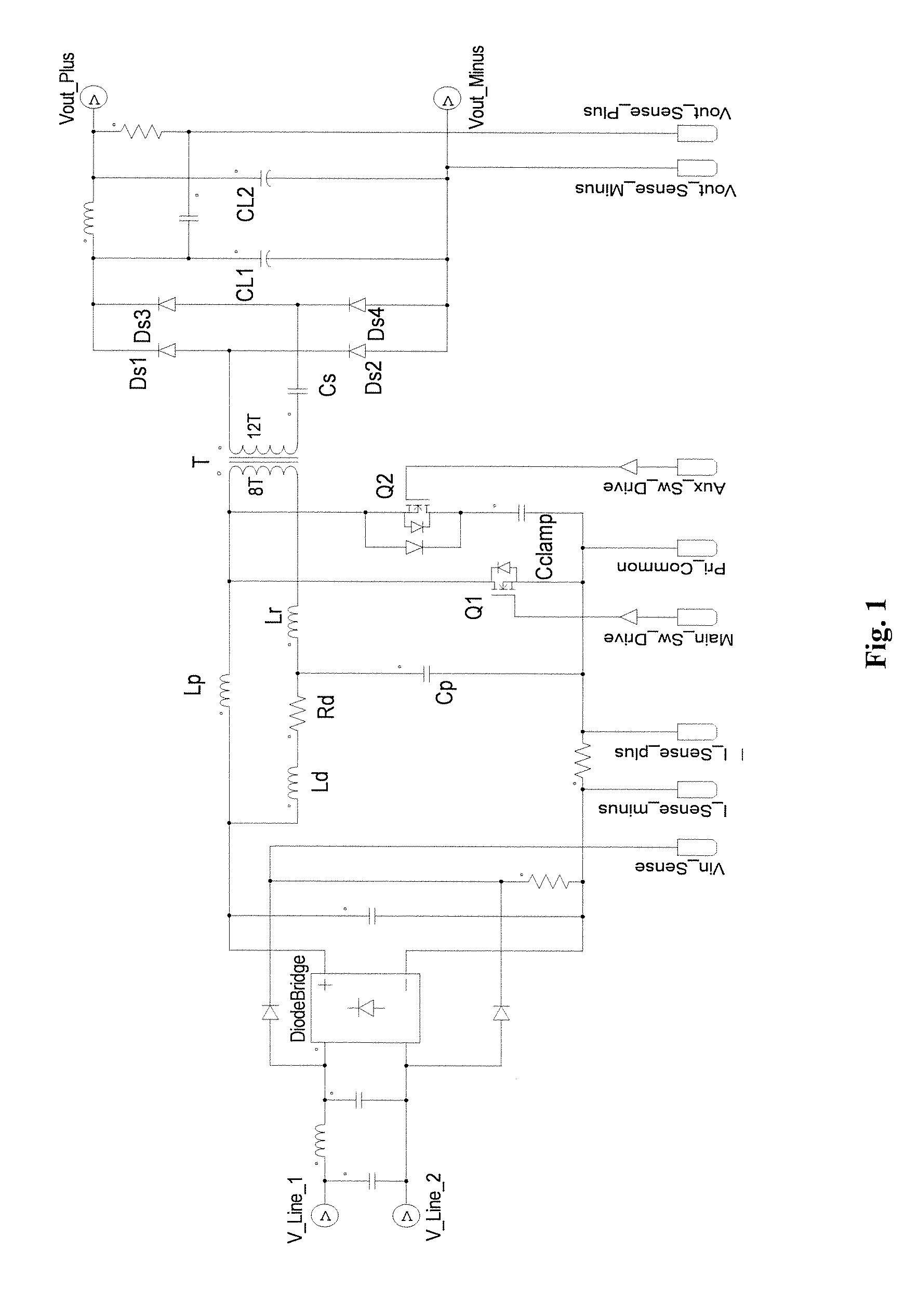
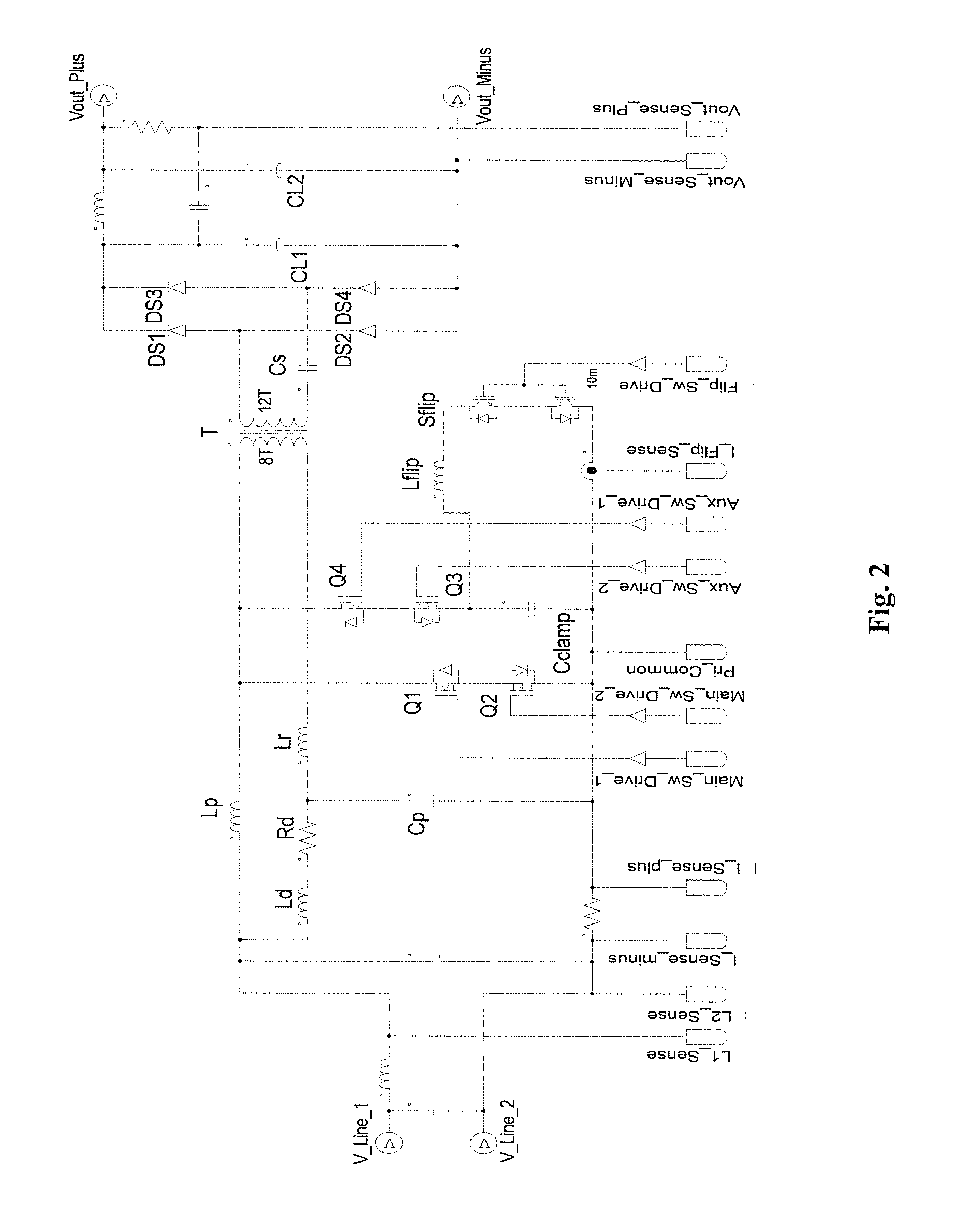
[0048]The basic schematic of one aspect of the invention is shown in FIG. 6. The converter is connected to an AC source by its input terminals. Four diodes Dp1, Dp2, Dp3, and Dp4 form a full bridge rectifier to rectify the AC source voltage to create a unipolar rectified sine wave voltage. A Power Factor Correction (PFC) inductor Lp is connected to one output of the bridge rectifier. A power transformer T has magnetization inductance Lm, primary winding Np and secondary winding Ns. Its primary winding is connected in series with a small valued resonant inductor Lr and they are then connected to the PFC inductor and a DC blocking capacitor Cp. A damper circuit consisting of a series connection of a resistor Rd and high frequency blocking inductor Ld is connected between the first the blocking capacitor Cp and the first output terminal of the full bridge rectifier. The damper circuit dampens the resonance of the transformer magnetizing inductance with the effective series capacitance ...


PUM


Abstract

Two versions of an isolated single stage converter AC / DC Power Factor Corrected (PFC) converter topology have been invented. One is with a full bridge rectifier at its input and the other is a True Bridgeless version. The two versions of the topology feature new configurations and circuitry including a simplified damper circuit and a clamp capacitor flipping circuit and control methods that allow them to realize improved single stage isolated power factor converters which are suitable for high power operation, features Zero Voltage Switching to maximize conversion efficiency and to minimize Electro-Magnetic Interference generation, does not need an additional circuit to limit the inrush current, achieves reasonably low input current Total Harmonic Distortion (THD), and is easy to control. The second version provides a true bridgeless single stage isolated power factor converter with even higher efficiency and lower input current THD.

Description

CROSS-REFERENCE TO RELATED APPLICATIONS[0001]This application claims the benefit of U.S. Provisional Patent Application No. 62 / 195,094 filed Jul. 21, 2015 and the subject matter thereof is incorporated herein by reference.FIELD OF THE INVENTION[0002]The present invention relates generally to isolated power factor corrected AC-DC converters and more particularly to single stage AC-DC converters and Bridgeless AC-DC converters.BACKGROUND OF THE INVENTION[0003]AC / DC Power Factor Corrected (PFC) converters are usually realized by using a full bridge rectifier followed by a boost converter to control the input current waveform to be sinusoidal and in phase with the input voltage waveform and then by an isolated DC / DC converter to provide galvanic isolation and output voltage regulation. This approach has been shown to be effective and efficient in both low power and higher power applications but involves several conversion stages which increases the cost. Also the boost converter stage d...

Claims


Application Information

Patent Timeline
Patent Type & Authority Applications(United States)
IPC IPC(8): H02M3/335H02M1/44H02M1/42
CPCH02M3/33546H02M2001/0009H02M1/44H02M1/42H02M3/33569H02M1/4241Y02B70/10H02M1/0009H02M1/0058H02M3/01H02M1/4208H02M1/425H02M1/4258H02M3/335
Inventor DAVIDSON, CHRISTOPHER DONOVAN
Owner DAVIDSON CHRISTOPHER DONOVAN
Why Eureka
Try Eureka