

Polymer foam and method for preparing the same
a polymer foam and polymer technology, applied in the field of polymer foam preparation, can solve the problems of low thermal stability and mechanical strength, cell rupture, low melt strength, etc., and achieve the effects of high melt strength, lower melt strength, and improved foamability
- Summary
- Abstract
- Description
- Claims
- Application Information
AI Technical Summary
Benefits of technology
Problems solved by technology
Method used
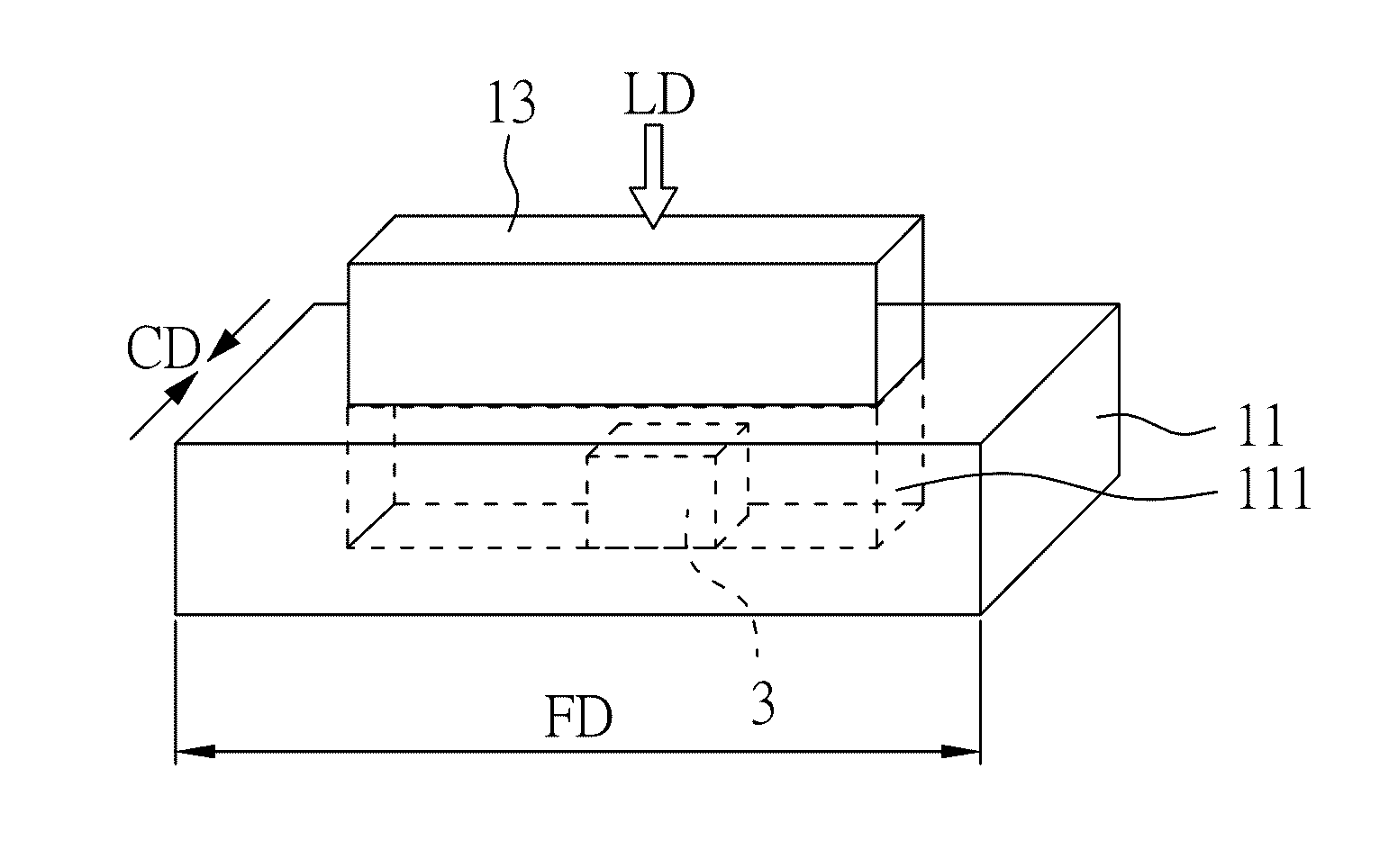
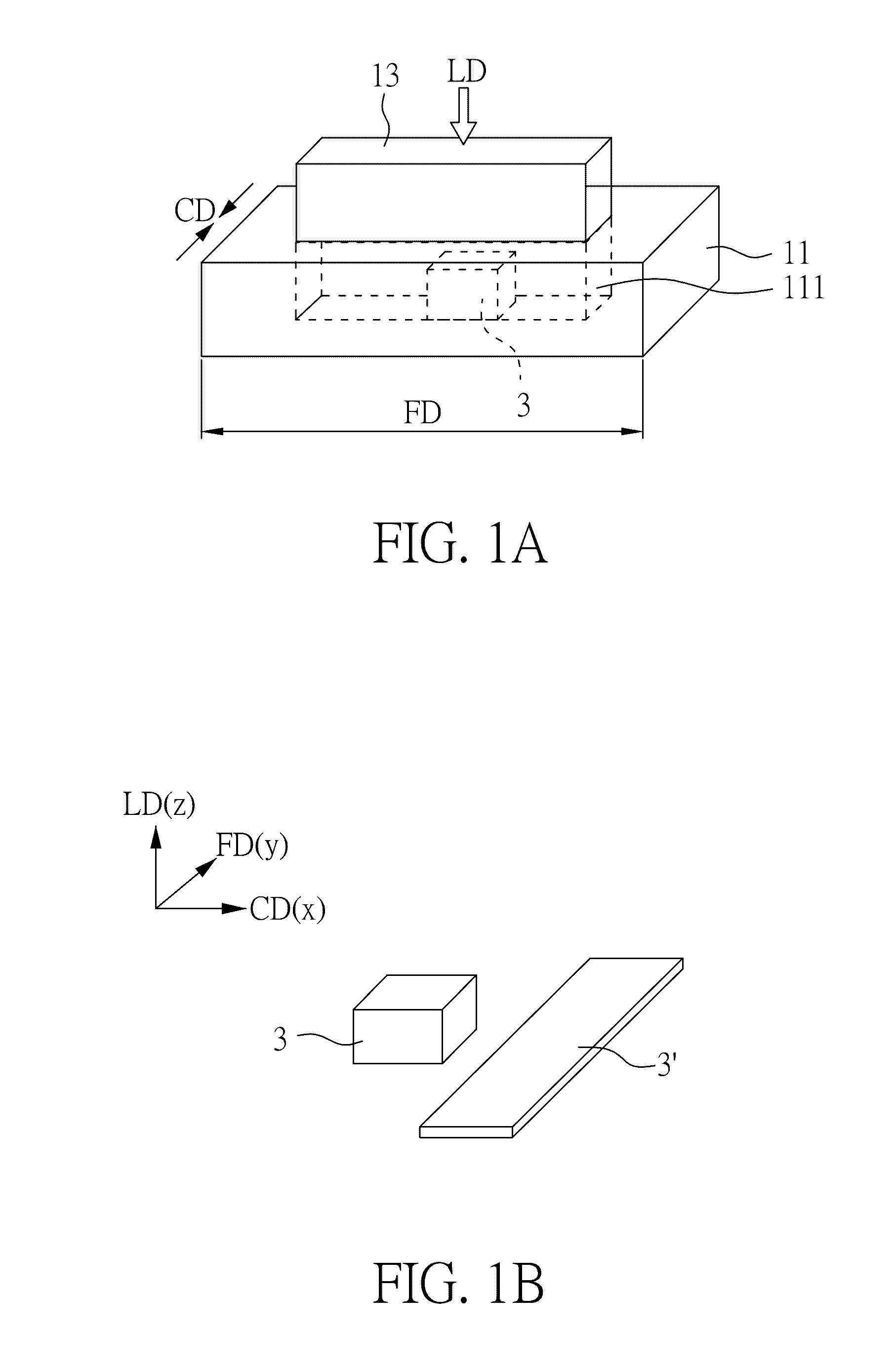
Image

Examples
example 1
Preparation of Polymer Foam with Only PP
Characterization
[0066]Foam density: The mass densities of obtained PP samples ρf were measured according to ASTM D792 involving weighing polymer foam in water using a sinker. ρf was calculated as follows:
ρf=aa-bρwater
where a is the apparent mass of specimen in air, b the apparent mass of specimen completely immersed in water.
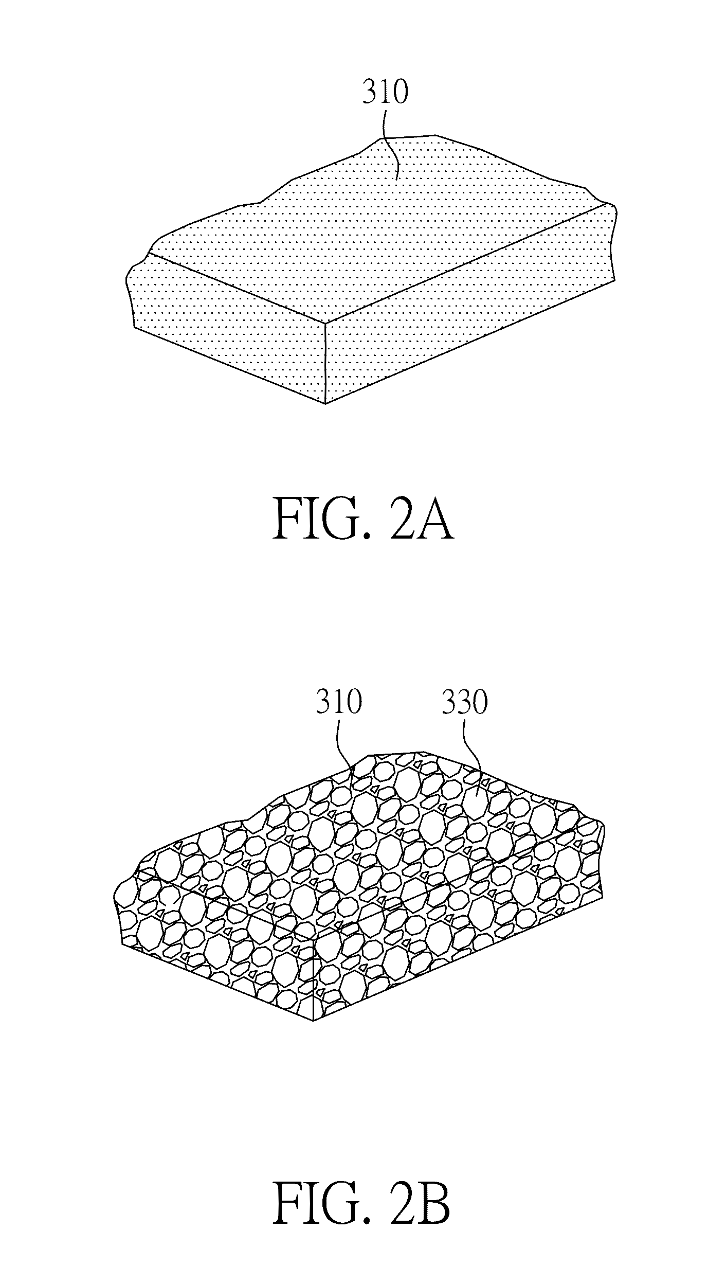
[0067]Scanning electron microscopy (SEM): The morphologies of the obtained PP foams were studied by SEM (Philips XL30). The samples were immersed in liquid nitrogen for 30 min and then fractured. The fractured surfaces were sprayed with a layer of gold for further observation by SEM.
[0068]Thermal mechanical analysis (TMA): The thermal stability of PIF and foamed samples were investigated by using a TMA (TA Instruments TMA 2940). The dimension change of samples was measured at a scanning rate of 5° C. / min from 30° C. to 180° C. under penetration mode.
[0069]Differential Scanning Calorimetry (DSC): The TA Q200 DSC was used to...
example 2
Preparation of Polymer Foam with a Composite Comprising PP and MWCNT
Characterization
[0089]All the characterization methods used in the present example are similar to those illustrate in Example 1, and the differences are listed below.
[0090]SEM: The difference between Example 1 and present example is that the samples were immersed in liquid nitrogen for 10 min and then fractured in the present example.
[0091]DSC: The difference between Example 1 and present example is that samples were cut into 10-15 mg thin slices for DSC characterization in the present example.
[0092]XRD: The difference between Example 1 and present example is that the samples were scanned from 5° to 70° with an increment of 0.4°.
[0093]Polarizing microscopy: A Leitz 1720 Cryostat Microtome was utilized to prepare thin slices of PP sample. The PP samples were cooled down to −15° C., and then cut into 25 and 50 μm thin slices. The 25 μm slices were utilized to observe the crystal structure of PP sample before and after...
PUM
| Property | Measurement | Unit |
|---|---|---|
| temperature | aaaaa | aaaaa |
| pressure | aaaaa | aaaaa |
| temperature | aaaaa | aaaaa |
Abstract
Description
Claims
Application Information