Electrical system incorporating a single structure multimode antenna for wireless power transmission using magnetic field coupling

a multi-mode antenna and electrical system technology, applied in the direction of transformers, variable inductances, inductances, etc., can solve the problems of inefficient inconvenient wire interconnection, hazardous or impossible, etc., to facilitate the wireless transmission of electrical power and/or data, and increase the electrical impedance within the antenna

Active Publication Date: 2017-02-09
NUCURRENT INC
View PDF9 Cites 24 Cited by
  • Summary
  • Abstract
  • Description
  • Claims
  • Application Information

AI Technical Summary

Benefits of technology

[0026]In a preferred embodiment, various materials may be incorporated within the structure of the antenna to shield the coils from magnetic field and/or electromagnetic interference and, thus, further enhance the antenna's electrical performance. Specifically, magnetic field shielding materials, such as a ferrite material, may be positioned about the antenna structure to either block or absorb magnetic fields that create undesirable proximity effects that increase electrical impedance within the antenna. As will be discussed in more detail, these proximity effects generally increase electrical impedance within the antenna which results in a degradation of the quality factor. In addition, the magnetic field shielding materials may be positioned about the antenna structure to increase inductance and/or act as a heat sink within the antenna structure to minimize over heating of the antenna. Furthermore, such materials may be utilized to modify the magnetic field profile of the antenna. Modification of the magnetic field(s) exhibited by the single structure a

Problems solved by technology

Wireless energy transfer is useful in cases where the interconnection of wires may be inconvenient, hazardous or impossible.
However, near-field communication is often not optimal because prior art antennas that facilitate the wireless transfer of electrical power and/or data operate inefficiently.
In addition, data that is received may be incomplete or may become corrupted.
In addition, near-field communication generally suffers from reduced wireless transfer distances, i.e., the transmission range, and physical antenna orientation issues.
These inefficiencies of near field communication are largely due to the low quality factor of the prior art antennas in addition to the inefficient large size of prior art antennas.
In general, prior art near field communication antennas have a relatively large size that hinders efficient operation and wireless transmission.
Size and efficiency are often a tradeoff, a problem which becomes more acute when multiple wireless operations are desired, i.e., multiple modes of operation.
This general requirement for near perfect physical alignment of the transmitting and rece

Method used


Image

  • Electrical system incorporating a single structure multimode antenna for wireless power transmission using magnetic field coupling
  • Electrical system incorporating a single structure multimode antenna for wireless power transmission using magnetic field coupling
  • Electrical system incorporating a single structure multimode antenna for wireless power transmission using magnetic field coupling

Examples


example conditions

[0096]A. f1≧10f2,

[0097]B. Δf2≦0.5f2

[0098]C. Δf1≦f1 / 50

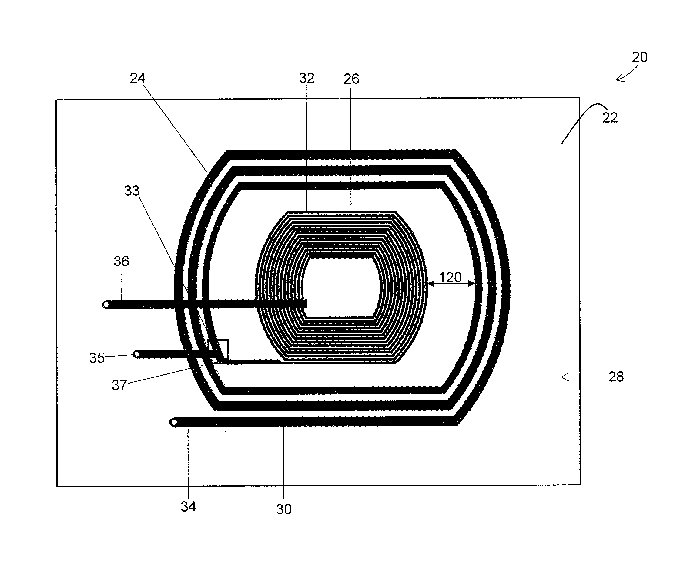
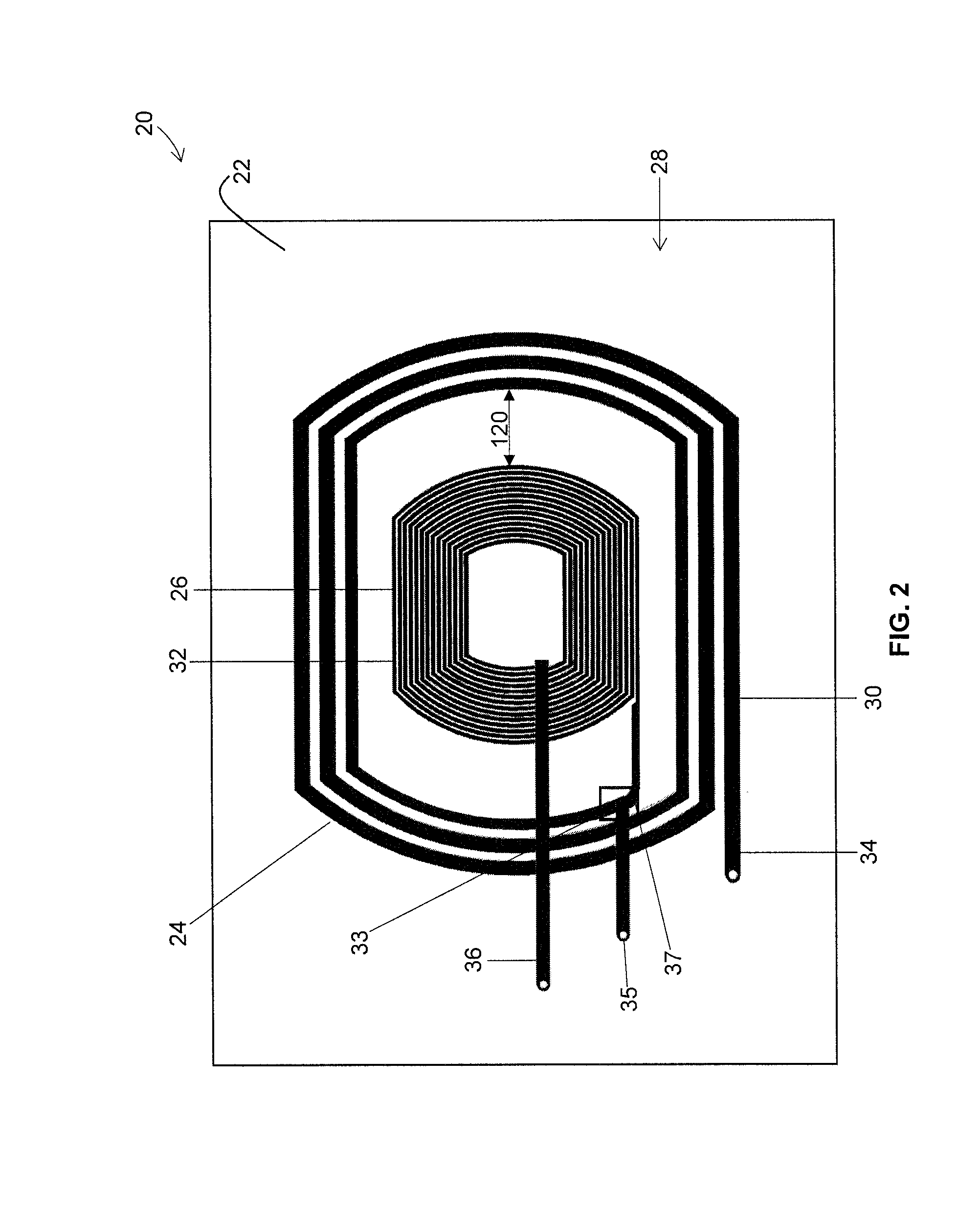
[0099]The selection circuit may be configured to select a desired antenna impedance Z2, at a desired antenna operating frequency f. For example, given the parameter equations as shown below, where C3 is the capacitance value of the selection circuit 118 for a desired antenna operating frequency, f (e.g. f=f1±Δf1 or f=f2±Δf2) and in which the impedance of the antenna is multiplied by a constant such as 1, 2, or 5. Thus, the selection circuit 118 can be designed such that the terminal connections are made at a certain impedance threshold value at a specific frequency or frequency band which may be determined by a multiplier constant.

12πfC3Constant×Z1or2

[0100]In general, the greater the difference in electrical impedance, the better discrimination in coil selection, thus the multiplier constant such be selected to create a discriminating electrical impedance that may be used to modify the operating frequency of the antenna. Thus, pr...


PUM


Abstract

An electrical system incorporating a single structure multiple mode antenna is described. The antenna is preferably constructed having a first inductor coil that is electrically connected in series with a second inductor coil. The antenna is constructed having a plurality of electrical connections positioned along the first and second inductor coils. A plurality of terminals is connected to the electrical connections that facilitate numerous electrical connections and enables the antenna to be selectively tuned to various frequencies and frequency bands.

Description

TECHNICAL FIELD[0001]The present disclosure relates generally to the wireless transmission of electrical energy and data. More specifically, this application relates to an antenna that facilitates the wireless transmission of data and electrical energy at multiple operating frequency bands.BACKGROUND[0002]Wireless energy transfer is useful in cases where the interconnection of wires may be inconvenient, hazardous or impossible. In recent years, applications employing near-field wireless power and / or data transmission have gained prominence in areas such as consumer electronics, medical systems, military systems and industrial applications. Near-field communication enables the transfer of electrical energy and / or data wirelessly through magnetic field induction between a transmitting antenna and a corresponding receiving antenna. Near-field communication interface and protocol modes are defined by ISO / IEC standard 18092.[0003]However, near-field communication is often not optimal bec...

Claims


Application Information

Patent Timeline
IPC IPC(8): H01Q7/00H01Q1/38
CPCH01Q7/005H01Q1/38H01Q7/00H01F38/14H02J50/10H01F27/38H01F29/02H02J50/12
Inventor SINGH, VINITPERALTA, ALBERTORAJAGOPALAN, AJITLUZINSKI, JASONBABCOCK, JACOBFRYSZ, CHRISTINE A.
Owner NUCURRENT INC
Why Eureka
Try Eureka