Inspection Apparatus, Inspection Method and Manufacturing Method

Active Publication Date: 2017-02-16
ASML NETHERLANDS BV
View PDF3 Cites 62 Cited by
  • Summary
  • Abstract
  • Description
  • Claims
  • Application Information

AI Technical Summary

Benefits of technology

[0018]Such an apparatus can be used to perform so-called “lensless” imaging. This avoids the difficulties associated with providing imaging optics for the shorter wavelengths. The image obtained and used to identify

Problems solved by technology

Often defects are related to certain ‘hot spots’ on a substrate, so that metrology efforts can be concentrated on those areas.
The dimensions of modern product structures are so small that they cannot be imaged by

Method used


Image

  • Inspection Apparatus, Inspection Method and Manufacturing Method
  • Inspection Apparatus, Inspection Method and Manufacturing Method
  • Inspection Apparatus, Inspection Method and Manufacturing Method

Examples


Embodiment Construction

[0038]Before describing embodiments of the invention in detail, it is instructive to present an example environment in which embodiments of the present invention may be implemented.

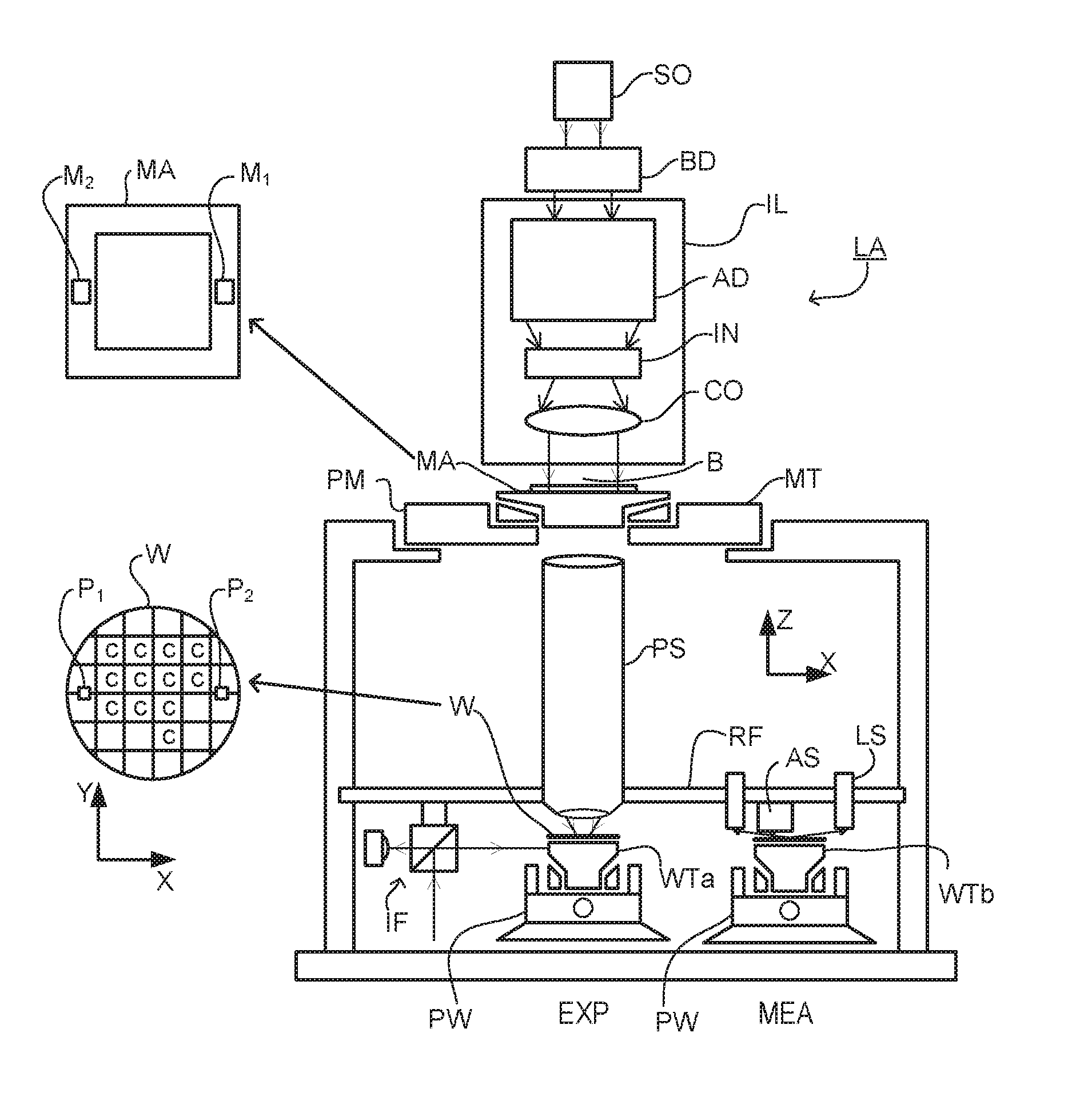
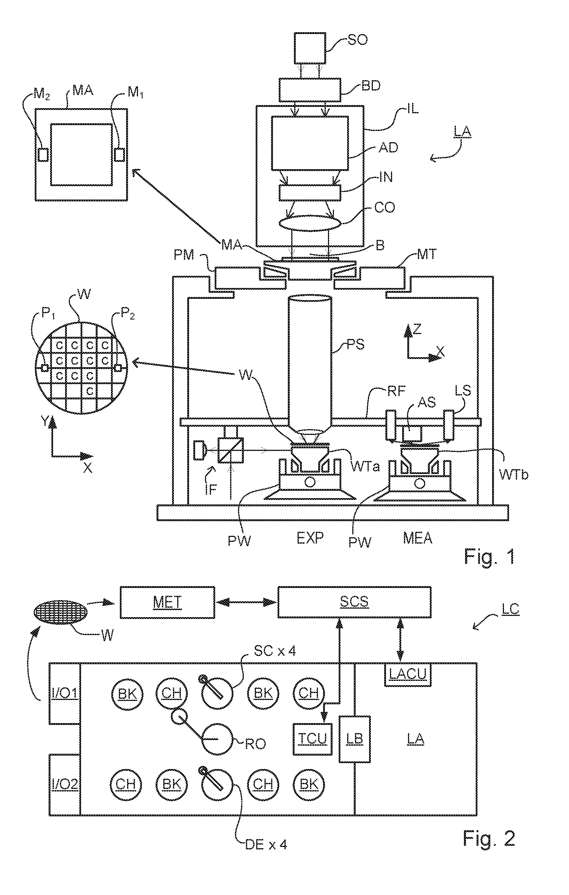
[0039]FIG. 1 schematically depicts a lithographic apparatus LA. The apparatus includes an illumination system (illuminator) IL configured to condition a radiation beam B (e.g., UV radiation or DUV radiation), a patterning device support or support structure (e.g., a mask table) MT constructed to support a patterning device (e.g., a mask) MA and connected to a first positioner PM configured to accurately position the patterning device in accordance with certain parameters; two substrate tables (e.g., a wafer table) WTa and WTb each constructed to hold a substrate (e.g., a resist coated wafer) W and each connected to a second positioner PW configured to accurately position the substrate in accordance with certain parameters; and a projection system (e.g., a refractive projection lens system) PS configured t...


PUM


Abstract

A product structure (407, 330′) is formed with defects (360-366). A spot (S) of EUV radiation which is at least partially coherent is provided on the product structure (604) to capture at least one diffraction pattern (606) formed by the radiation after scattering by the product structure. Reference data (612) describes a nominal product structure. At least one synthetic image (616) of the product structure is calculated from the captured image data. Data from the synthetic image is compared with the reference data to identify defects (660-666) in the product structure. In one embodiment, a plurality of diffraction patterns are obtained using a series overlapping spots (S(1)-S(N)), and the synthetic image is calculated using the diffraction patterns and knowledge of the relative displacement. The EUV radiation may have wavelengths in the range 5 to 50 nm, close to dimensions of the structures of interest.

Description

BACKGROUND[0001]Field of the Invention[0002]The present invention relates to inspection apparatus and methods usable, for example, to perform defect detection in the manufacture of devices by lithographic techniques. The invention further relates to an illumination system for use in such inspection apparatus and to methods of manufacturing devices using lithographic techniques. The invention yet further relates to computer program products for use in implementing such methods.[0003]Background Art[0004]A lithographic apparatus is a machine that applies a desired pattern onto a substrate, usually onto a target portion of the substrate. A lithographic apparatus can be used, for example, in the manufacture of integrated circuits (ICs). In that instance, a patterning device, which is alternatively referred to as a mask or a reticle, may be used to generate a circuit pattern to be formed on an individual layer of the IC. This pattern can be transferred onto a target portion (e.g., includi...

Claims


Application Information

Patent Timeline
IPC IPC(8): G03F7/20G01N21/47G01N21/956
CPCG03F7/7065G01N21/95607G01N2201/12G01N2201/06113G01N21/4788G03F1/24G03F1/84G02B21/365G02B21/367G01N2021/95615G21K2207/00G21K7/00G21K2207/005
Inventor QUINTANILHA, RICHARD
Owner ASML NETHERLANDS BV
Why Eureka
Try Eureka