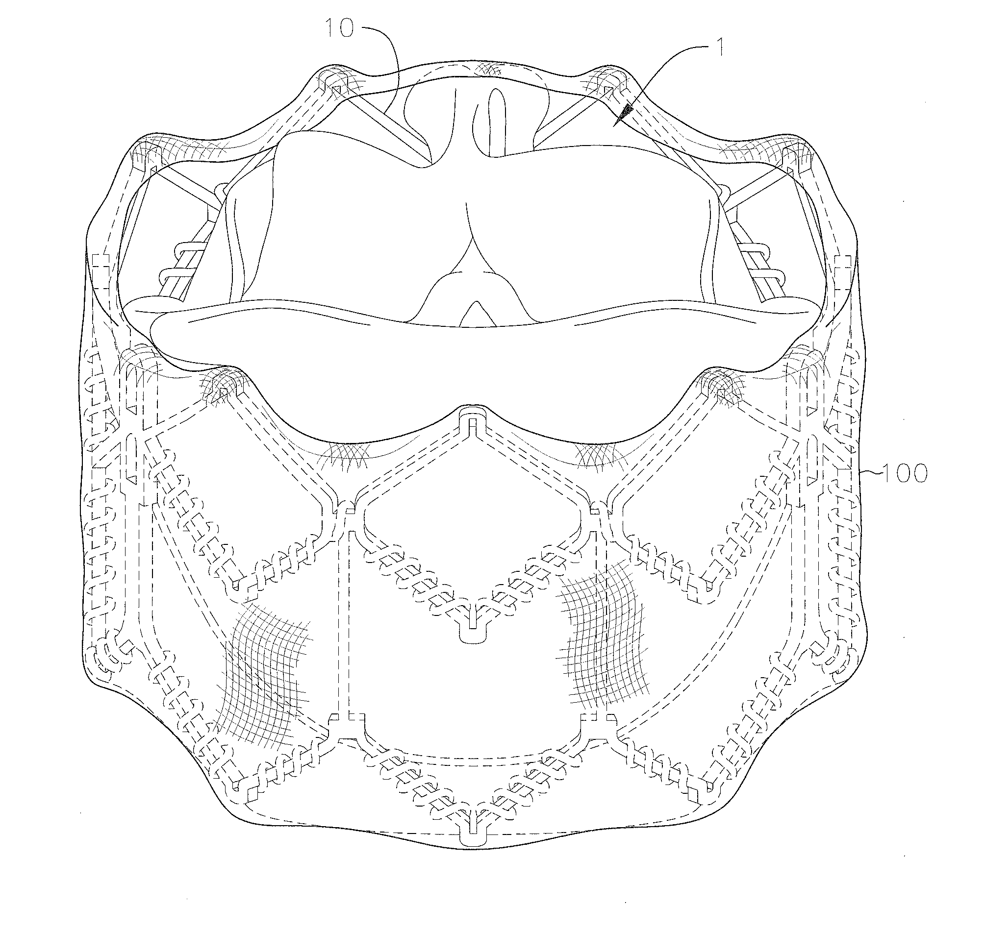
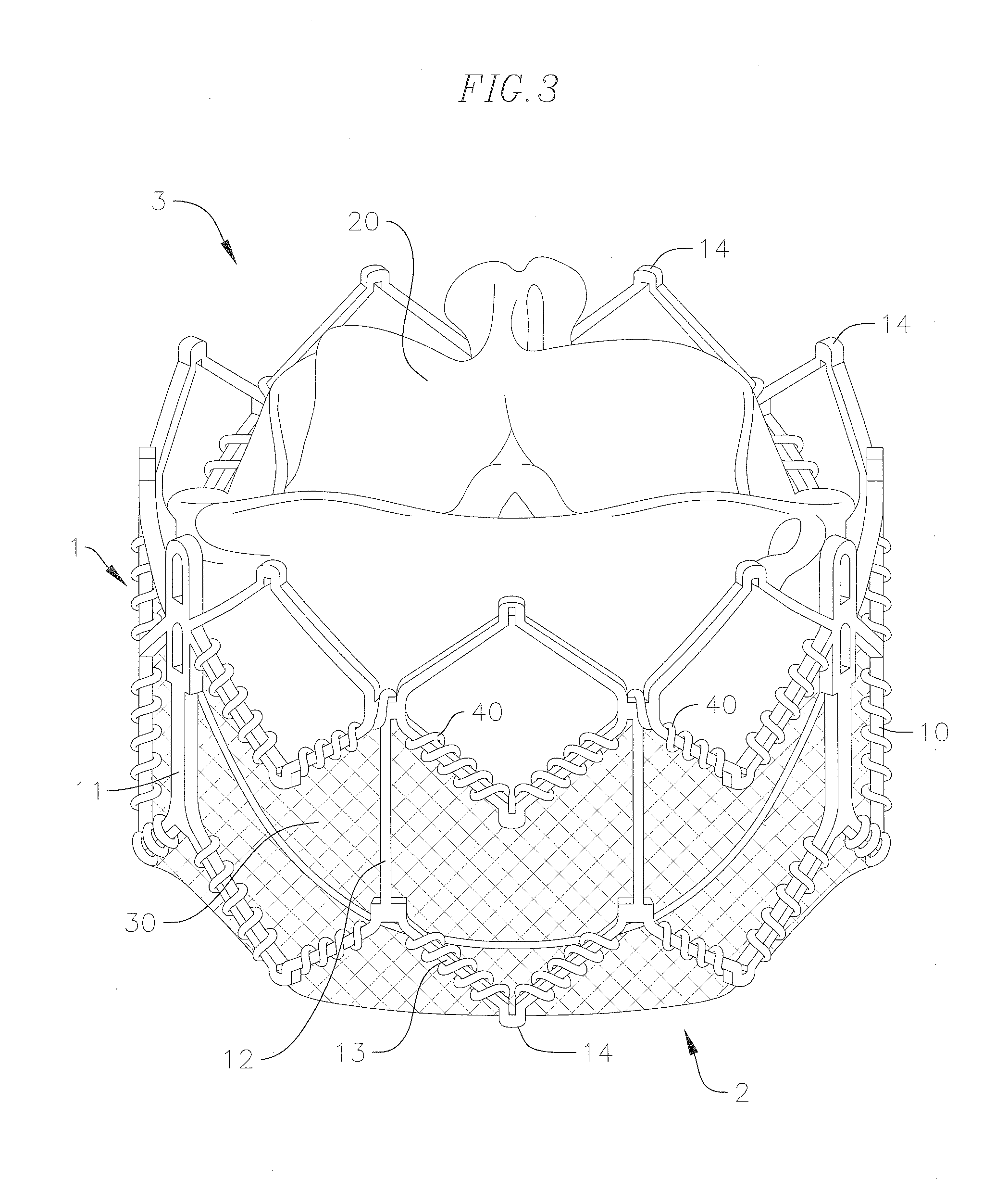
Covering and assembly method for transcatheter valve

Active Publication Date: 2017-03-02
EDWARDS LIFESCIENCES CORP
View PDF3 Cites 24 Cited by
  • Summary
  • Abstract
  • Description
  • Claims
  • Application Information

AI Technical Summary

Benefits of technology

[0018]According to embodiments of the invention, mitral valve replacement can be more effectively realized by providing measures to bet

Problems solved by technology

Due to the large pressure differential between the left ventricle and the left atrium during ventricular contraction, a possibility of prolapse, or eversion of the leaflets of the mitral valve back into the atrium, arises.
Complications of the mitral valve can potentially cause fatal heart failure.
Replacement of a mitral valve is difficult in many respects, for example, due to the physical structure of the valve and difficulties in accessing the valve.
The most prominent obstacle for mitral valve replacement is anchoring or retaining the valve in position, due to the valve being subject to a large cyclic load.
Also, the movement and rhythmic load can fatigue materials, leading to fractures of the implanted valve.
If the orientation of a mitral prosthesis is unintentionally shifted, blood flow between the left atrium and the left ventricle can be obstructed or otherwise negatively affected.
While puncturing the tissue in or around the mitral valve an

Method used


Image

  • Covering and assembly method for transcatheter valve
  • Covering and assembly method for transcatheter valve
  • Covering and assembly method for transcatheter valve

Examples


second embodiment

[0050]An alternative approach is provided in the embodiment illustrated in FIGS. 6 and 7. FIGS. 6 and 7 show the invention, which includes a casing or covering 200 that is a stand-alone accessory that can be attached to an existing valve prosthesis by a practitioner or other end user. A main body 210 of the covering 200 can be made of a biocompatible cloth or other suitable biocompatible material with low friction and low abrasive properties. The cloth or other material used for the body 210 can be constructed of a stretchable material, possibly a knitted or otherwise breathable material, and / or a material that will promote ingrowth after implantation. The body 210 of the covering 200 is a generally rectangular cloth with a central portion 211 sized and shaped to wrap around the entire prosthetic valve 1 in a circumferential direction. The body 210 further includes loop portions 212 on one or both ends of the central portion 211, that will be positioned approximate the inflow and ou...

third embodiment

[0053]FIGS. 8A, 8B, and 9 show the invention, which includes another coat or covering 300 that is a stand-alone accessory attachable to an existing valve prosthesis by an end user. A main body 310 of the covering 300 can be similar in size and shape to the main body 210 of the covering 200 in FIGS. 6 and 7, and can be made of a biocompatible cloth or other material with similar properties as those discussed with respect to the body 210 of the covering 200. A length of a central portion 311 of the body 310 of the covering 300 is sufficient for circumferentially wrapping the covering 300 around the entire prosthetic valve 1.

[0054]The covering 300 differs from the covering 200 in FIGS. 6 and 7 in the construction of the attachment mechanisms for attaching the respective coverings to the prosthetic valve 1. Rather than the loop portions 212 and the strings or threads 220, the covering 300 instead has an open first end 312 with a plurality of stringed or threaded loops 320 attached there...

fourth embodiment

[0071]Using a covering with loops can reduce the time it takes to thread or transmit sutures from one side of the valve frame and covering to the other side of the valve frame and covering. Furthermore, the suturing process becomes easier and quicker for the end user, because the sutures only need be threaded through the large loops instead of through an eye of a needle or other sharp threading tool, and use of sharp tools around the valve leaflet tissue is no longer necessary, eliminating the possibility of unintended damage to the leaflets caused by any such sharp tools, and thereby improving the overall performance of the implanted valves in general. In addition, since the loops are threaded through and pre-positioned on the covering during manufacturing, accuracy of the through holes for the sutures can be pre-set, leading to more accurate placement of the sutures and less errors.

[0072]While the above embodiments better protect the tissue surrounding the prosthetic valve implan...


PUM


Abstract

A covering layer for a transcatheter heart valve is in various embodiments configured to prevent or reduce damage to the native valve tissue around the site where the prosthetic valve is implanted. In some cases, prosthetic valves are manufactured with the covering layer attached. Other covering layers are stand-alone accessories that can be mounted onto pre-existing prosthetic valves by an end user. Covering layers that can be mounted by an end user are provided with various features that can facilitate easier attachment of the covering layer to the prosthetic valve, which further reduces the possibility of damage to the covering layer or to the valve. Another covering is provided with two layers in order to insulate and protect the native tissue surrounding the implant from damage due to friction or abrasion, and/or other movement driven wear.

Description

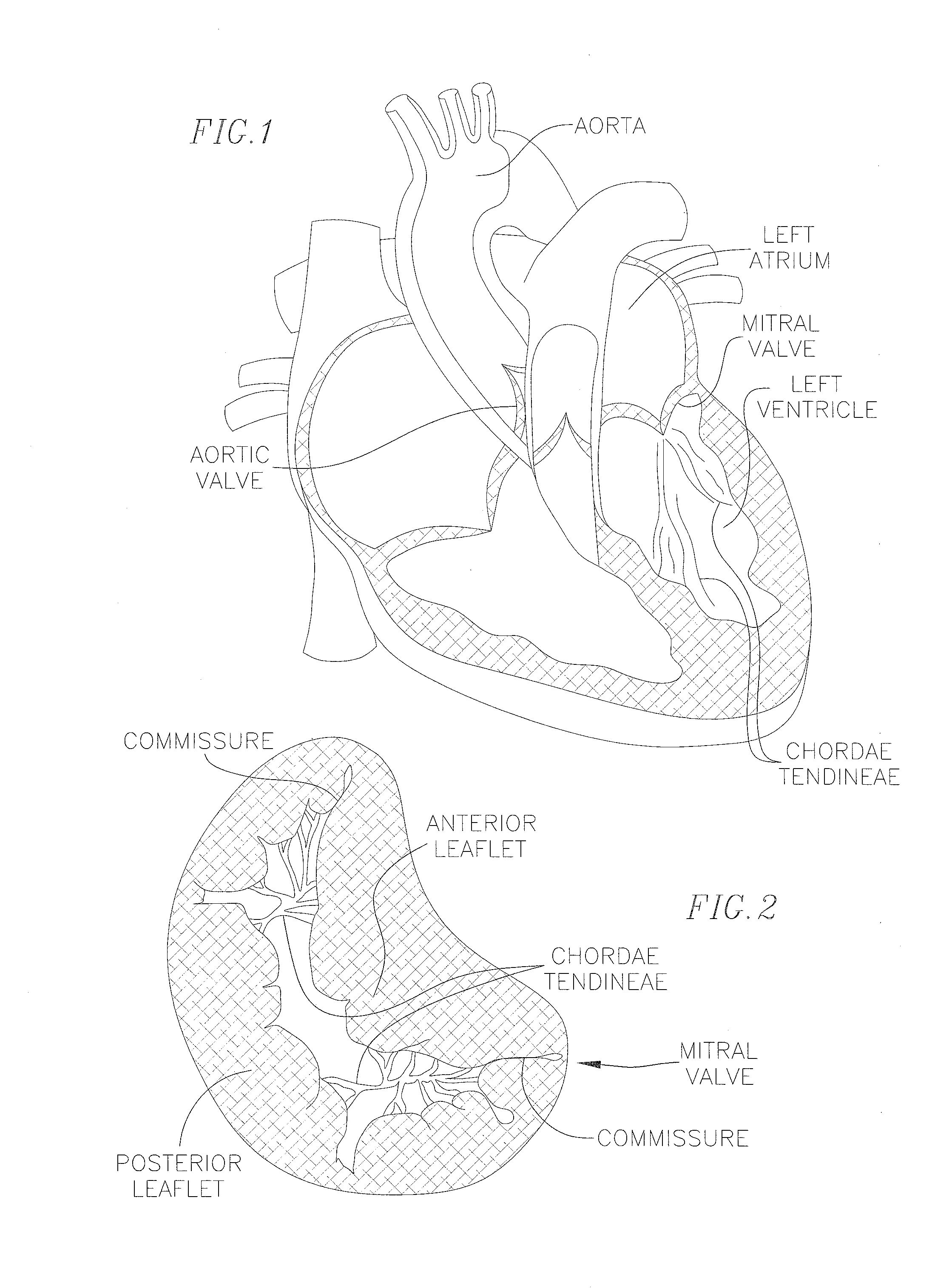
CROSS-REFERENCE TO RELATED APPLICATION(S)[0001]The present application claims priority to and the benefit of U.S. Provisional Patent Application Ser. No. 62 / 209,180, filed Aug. 24, 2015, the contents of which are hereby incorporated by reference in their entirety.BACKGROUND[0002]Field[0003]The invention relates generally to medical devices and procedures pertaining to prosthetic heart valves. More specifically, the invention relates to replacement of heart valves that have malformations and / or dysfunctions. Embodiments of the invention relate to prosthetic heart valves for replacing a mitral valve in the heart, or for replacing other valves where an additional ring or other anchor is utilized together with the prosthetic heart valve at the implant site, and assembly methods for preparing such prosthetic heart valves for implantation.[0004]Description of Related Art[0005]Referring first generally to FIGS. 1 and 2, the mitral valve controls the flow of blood between the left atrium an...

Claims


Application Information

Patent Timeline
IPC IPC(8): A61F2/24
CPCA61F2/2409A61F2220/0075A61F2/2418A61F2/2415A61F2250/006A61F2250/0069A61F2230/0091A61F2/24A61F2/2412
Inventor TAYEB, LIRONTAMIR, ILAN
Owner EDWARDS LIFESCIENCES CORP
Why Eureka
Try Eureka