Surface-modified metal and method for modifying metal surface

Active Publication Date: 2017-03-02
SUMITOMO RUBBER IND LTD
View PDF2 Cites 5 Cited by
  • Summary
  • Abstract
  • Description
  • Claims
  • Application Information

AI Technical Summary

Benefits of technology

[0023]The surface-modified metals of the present invention are characterized in that the surface of the surface-modified metals is at least partially provided with a treatment layer having a thickness of 50 to 800 nm, formed by treating the surface of metals with a silane coupling agent, followed by adsorbing a hydrogen abstraction type photopolymerization initiator onto the surface and then polymerizing a monomer; or a treatment layer having a thickness of 50 to 800 nm, formed by treating the surface of metals with a silan

Problems solved by technology

When a medical device such as a catheter or guide wire is inserted into the body, the medical device may damage the tissue or the like in the body and produce inflammation or cause pain to the patient.
Moreover, the insertion of a syringe needle into the body may also damage the tissue or the like in the body and cause pain to the patient.
Furthermore, if the inner surface of a syring

Method used


Image

  • Surface-modified metal and method for modifying metal surface
  • Surface-modified metal and method for modifying metal surface
  • Surface-modified metal and method for modifying metal surface

Examples


Example

Example 1

[0075]The surface of a SUS flat plate (10 cm square, 1 mm in thickness) was washed with acetone and dried.

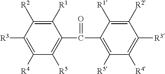
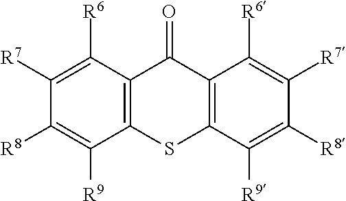
[0076]The plate was immersed in a 2% by mass aqueous solution of (3-acryloyloxypropyl)trimethoxysilane containing 2% by mass of acetic acid for 10 minutes, taken out and dried for 24 hours. The plate was then washed with acetone. The treated SUS plate was immersed in a 1% by mass solution of 2,4-diethylthioxanthone in acetone, taken out and dried.

[0077]On the surface of the dried SUS plate was dropped an aqueous solution of potassium 3-sulfopropyl methacrylate (1.25 M). Then, the surface was covered with a 1 mm thick glass plate, and the covered surface was irradiated with LED-UV (5 mW / cm2) having a wavelength of 365 nm for 6 hours to cause surface-initiated radical polymerization. Subsequently, the surface was washed with water to wash away unreacted monomer and the like. In this manner, a surface-modified metal was prepared.

Example

Example 2

[0078]The surface of a SUS flat plate (10 cm square, 1 mm in thickness) was washed with acetone and dried.

[0079]The plate was immersed in a 2% by mass aqueous solution of (3-acryloyloxypropyl)trimethoxysilane containing 2% by mass of acetic acid for 10 minutes, taken out and dried for 24 hours. The plate was then washed with acetone. The treated SUS plate was immersed in a 1% by mass solution of 2,4-diethylthioxanthone in acetone, taken out and dried.

[0080]On the surface of the dried SUS plate was dropped an aqueous solution of potassium 3-sulfopropyl methacrylate (1.25 M). Then, the surface was covered with a 1 mm thick glass plate, and the covered surface was irradiated with LED-UV (5 mW / cm2) having a wavelength of 365 nm for 12 hours to cause surface-initiated radical polymerization. Subsequently, the surface was washed with water to wash away unreacted monomer and the like. In this manner, a surface-modified metal was prepared.

Example

Example 3

[0081]The treatment with a silane coupling agent, the treatment with 2,4-diethylthioxanthone, and drying were carried out in the same manner as in Example 1, except that the SUS plate was changed to a SUS guide wire (core wire).

[0082]Subsequently, the dried guide wire was put in a glass vessel containing an aqueous solution of 2-(methacroyloxy)ethyl trimethylammonium chloride (1.25 M), and the vessel was sealed with a stopper. After argon substitution was performed for two hours to remove oxygen, the glass vessel was irradiated with LED-UV (5 mW / cm2) for 96 hours while being rotated, to cause surface-initiated radical polymerization. In this manner, a surface-modified metal was prepared.


PUM

PropertyMeasurementUnit
Thicknessaaaaaaaaaa
Fractionaaaaaaaaaa
Fractionaaaaaaaaaa

Abstract

Provided are surface-modified metals and methods for modifying a metal surface, which involve a lubricating surface layer chemically fixed to the metal surface to provide excellent lubricity and excellent lubricant durability, and further which have good productivity and good economic efficiency. Included is a surface-modified metal whose surface is at least partially provided with a treatment layer having a thickness of 50 to 800 nm, the treatment layer being formed by treating a surface of a metal with a silane coupling agent, followed by adsorbing a hydrogen abstraction type photopolymerization initiator onto the surface and then polymerizing a monomer.

Description

TECHNICAL FIELD[0001]The present invention relates to surface-modified metals and methods for modifying a metal surface.BACKGROUND ART[0002]Guide wires and other tools used for assisting insertion of medical devices such as catheters into the body are inserted into and optionally placed in blood vessels, respiratory tracts, urethra, and other body cavities or tissues. When a medical device such as a catheter or guide wire is inserted into the body, the medical device may damage the tissue or the like in the body and produce inflammation or cause pain to the patient. To ameliorate these problems, it has been desired to improve the sliding properties of the medical devices intended to be inserted into the body.[0003]Moreover, the insertion of a syringe needle into the body may also damage the tissue or the like in the body and cause pain to the patient. Furthermore, if the inner surface of a syringe needle, a metal tube in a medical device or equipment, or other metal devices exhibits...

Claims


Application Information

Patent Timeline
IPC IPC(8): A61L31/10A61L31/02A61L31/14C08F292/00
CPCA61L31/10C08F292/00A61L31/022A61L2420/02A61L2400/18A61L2400/10A61L31/14C08F2/48C08F120/34A61L29/085A61L29/14C08L33/08C08L33/10
Inventor MINAGAWA, YASUHISA
Owner SUMITOMO RUBBER IND LTD
Why Eureka
Try Eureka