Parallel motion heat energy power machine and working method thereof

a heat energy power machine and parallel motion technology, applied in the direction of machines/engines without rotary main shafts, steam generation using solar heat, etc., can solve the problems of limiting the improvement of power, heavy weight of whole machines, and difficult heat efficiency improvement, so as to reduce energy loss, reduce manufacturing costs, and simple structure

Active Publication Date: 2017-03-02
GUO YUANJUN
View PDF4 Cites 11 Cited by
  • Summary
  • Abstract
  • Description
  • Claims
  • Application Information

AI Technical Summary

Benefits of technology

[0021]The advantages of the invention is: 1. the working medium can be repeatedly used without pollution; 2. the heat energy conversion efficiency is 65%-98%; 3. the output power can be adjusted by adjusting the capacity and number of the machine cylinder according to desired power; 4, the output power can be adjusted within the maximum power range by adjusting the injecting liquid; 5. the machine works by gasifying the working medium, which does not generate knocking during the whole process; 6. the machine has a simple structure, low manufacturing cost, and uses the automatic exhaust function to reduce energy loss; 7. the working power of the present invention is twice than that of the single cylinder; 8. conventional energy consumption can be replaced, which is economic, energy-saving, environment friendly, and less noisy.

Problems solved by technology

The whole machine is heavy and large.
The heat efficiency is hard to improve.
The flow of steam is restrained, which limits the improvement of the power.
Internal combustion engine: It has a complicated structure, a high requirement of fuel, and strict requirement of the cleanliness of fuel.
It pollutes the environment.
Meanwhile, the mainly existing problems and defects of Stirling engine are as follows: the manufacturing cost is high; the working medium sealing technology is difficult the reliability and serving life of the sealing part have problems; the material cost is high; the power adjusting control system is complex; the machine is heavy; the costs of the expansion chamber, the compression chamber, the heater, the cooling chamber, the regenerator, etc. are high; and the heat loss is twice to three times than that of an internal combustion engine.

Method used


Image

  • Parallel motion heat energy power machine and working method thereof
  • Parallel motion heat energy power machine and working method thereof

Examples


embodiment 1

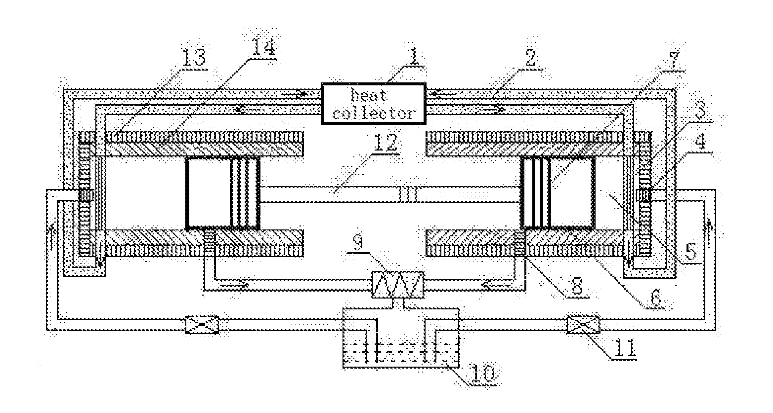
[0026]A parallel motion heat energy power machine includes a heat collector 1, insulating pipes 2. gasification reactors 3, atomizers 4, cylinders 5, pistons 6, piston rings 7, automatic exhaust valves 8, cooler 9, liquid storage tank 10, pressure pumps 11, push-pull rod 12, insulating layer 13, and a housing 14. Two cylinders 5 are oppositely arranged on housing 14 in parallel Piston 6 is arranged inside cylinders 5. Piston 6 is provided with piston rings 7. Pistons 6 are arranged on both ends of push-pull rod 12. Heat collector 1 is connected to gasification reactor 3 through insulating pipe 2. Atomizer 4 is arranged on the air inlet end of gasification reactors 3. Atomizer 4 is connected to pressure pumps 11 through the pipes. Pressure pump 11 is connected to liquid storage tank 10 through the pipes. Gasification reactor 3 is arranged on the top dead center of cylinder 5. Automatic exhaust valve 8 is arranged on the bottom dead center of cylinder 5. Automatic exhaust valve 8 is c...

embodiment 2

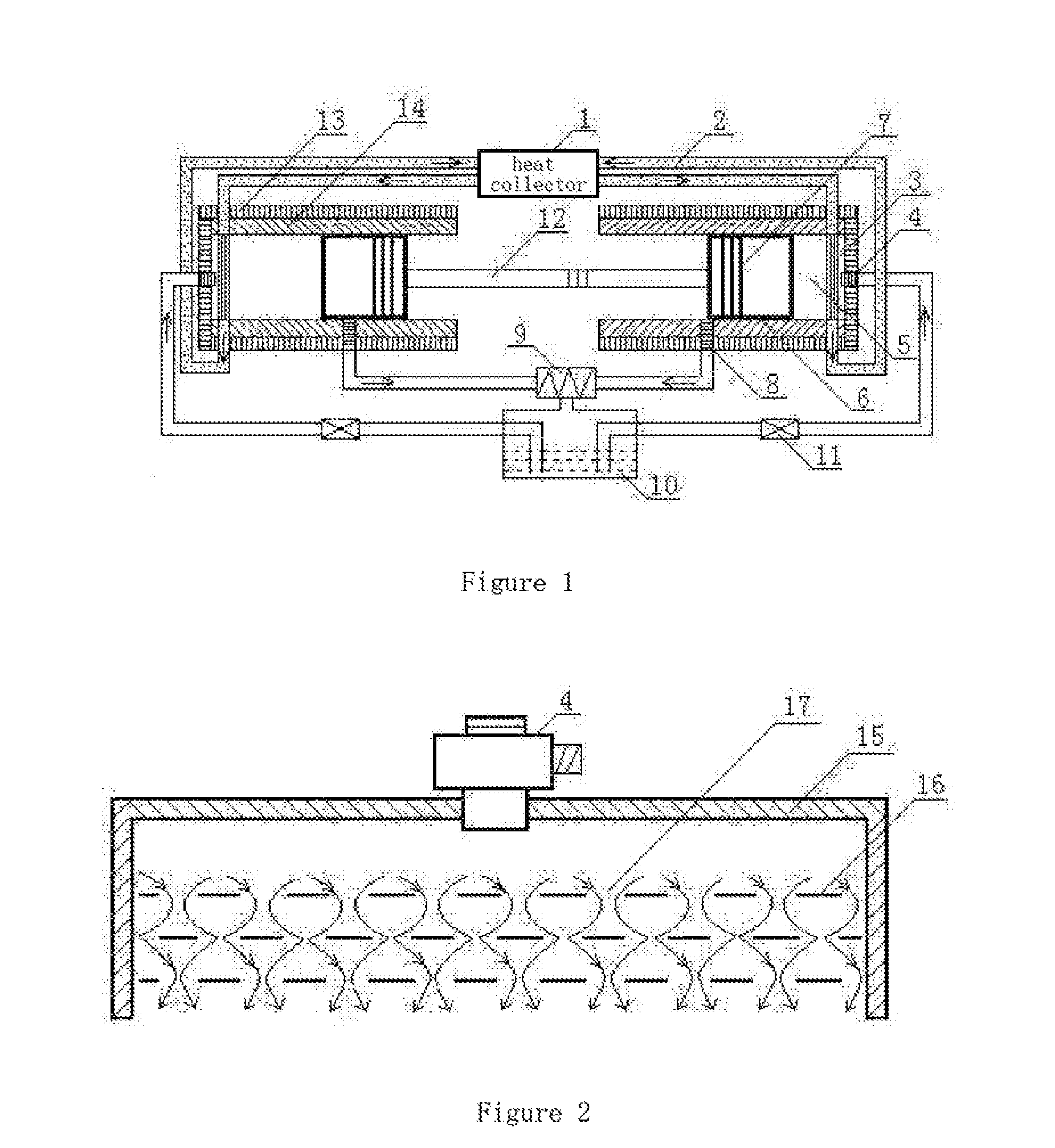
[0027]The parallel motion heat energy power machine as described in Embodiment 1, the gasification reactor includes pressure vessel 15, gasification conducting strip 16, gas hole 17, atomizer 4. Gasification conducting strip 16 is arranged on pressure vessel 15. Gas hole 17 is arrayed on gasification conducting strip 16. Atomizer 4 is arranged on the air inlet end of pressure vessel 15. Pressure pump 11 is associated with push-pull rod 12. pressure pump 11 opens and closes once whenever the circulation is completed. Push-pull rod 12 is provided with a transmission shaft, which connects to the rotator of the generator to cut the magnetic induction lines. Cooler 9 uses the natural water cooling method or the condenser.


PUM


Abstract

A parallel motion heat energy power machine and a working method thereof, includes a heat collector, an insulating pipe, a gasification reactor, an atomizer, a cylinder, a piston, a piston ring, an automatic exhaust valve, a cooler, a liquid storage tank, a pressure pump, a push-pull rod, an insulating layer, and a housing. The two cylinders are oppositely arranged on the housing in parallel. The piston is arranged inside the cylinder. The piston is provided with the piston ring. The pistons are arranged on both ends of the push-pull rod. The heat collector is connected to the gasification reactor through the insulating pipe. The atomizer is arranged on the air inlet end of the gasification reactor. The parallel motion heat energy power machine and working method thereof has a high heat-energy conversion efficiency. It is energy-saving, environmentally friendly, and less noisy.

Description

CROSS REFERENCE TO RELATED APPLICATIONS[0001]This application is the national phase entry of International Application No. PCT / CN2014 / 087197, filed on Sep. 23, 2014, which is based upon and claims priority to CN 201410177409.0, filed on Apr. 30, 2014, the entire contents of which are incorporated herein by reference.TECHNICAL FIELD[0002]The invention relates to the field of thermal energy power equipment, especially the power machine which can convert heat energy from the solar energy, the geothermal, the high-temperature gas generated by burning of combustibles, the thermal energy or the exhaust gas of internal combustion engine, and the high-temperature gas discharged from factory into the kinetic energy.BACKGROUND[0003]Conventional power equipment includes the steam engines, internal combustion engines, and external combustion engines.[0004]Steam engine: It cannot work without the boiler. The whole machine is heavy and large. The pressure and the temperature of the new steam cann...

Claims


Application Information

Patent Timeline
Patent Type & Authority Applications(United States)
IPC IPC(8): F01K3/02F03G7/04F01B29/12F01K13/00F01B31/08F01K23/06F01K3/18F03G6/00F01B31/28
CPCF01K3/02F03G6/003F03G7/04F01B29/12F01K13/006F01B31/08F01K23/064F01K23/065F01K3/18F01B31/28F02G1/044F01B23/10F02B71/04F01B11/004F02B63/041Y02E10/46F01K7/36F22B1/006F02B39/085F03G4/035F03G6/004
Inventor GUO, YUANJUN
Owner GUO YUANJUN
Why Eureka
Try Eureka