Adaptive additive manufacturing process using in-situ laser ultrasonic testing

an additive manufacturing and in-situ technology, applied in the field of in-situ laser ultrasonic testing, can solve the problems of non-destructive x-ray and neutron diffraction techniques, inability to carry out in-situ, and material removal,

Inactive Publication Date: 2017-03-02
SIEMENS ENERGY INC
View PDF3 Cites 27 Cited by
  • Summary
  • Abstract
  • Description
  • Claims
  • Application Information

AI Technical Summary

Problems solved by technology

Physical characteristic of a completed part of concern include defects (voids, cracks etc.) as well as an amount of residual stress, in part because residual stress can cause warping and premature cracking.
However, this requires material removal and is therefore at least semi-destructive.
X-ray and neutron diffraction techniques are non-destructive, but they are expensive and cannot be carried out in-situ.
Consequently, magnetic testing is necessarily limited to ferromagnetic materials.

Method used


Image

  • Adaptive additive manufacturing process using in-situ laser ultrasonic testing
  • Adaptive additive manufacturing process using in-situ laser ultrasonic testing
  • Adaptive additive manufacturing process using in-situ laser ultrasonic testing

Examples


Embodiment Construction

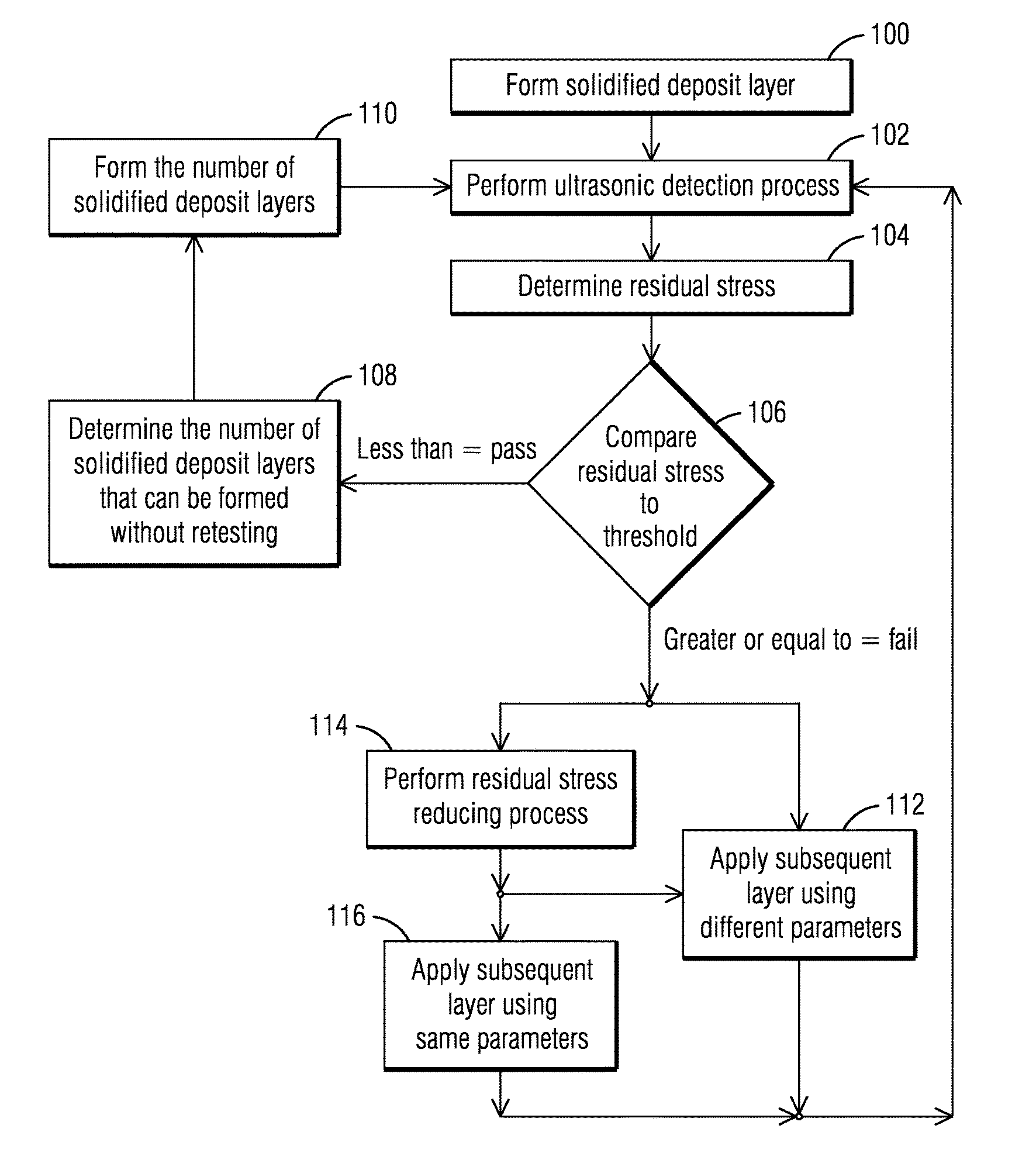
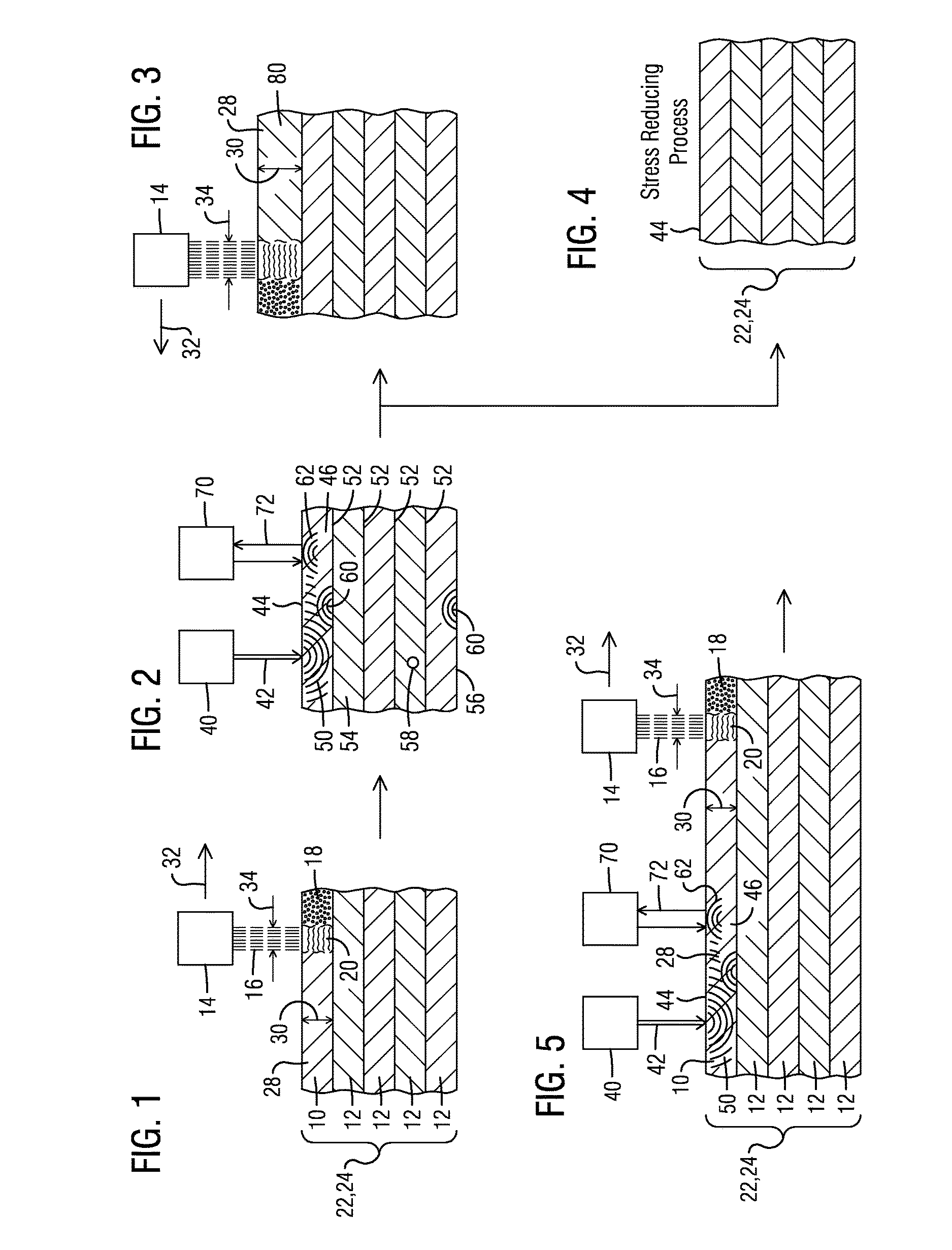
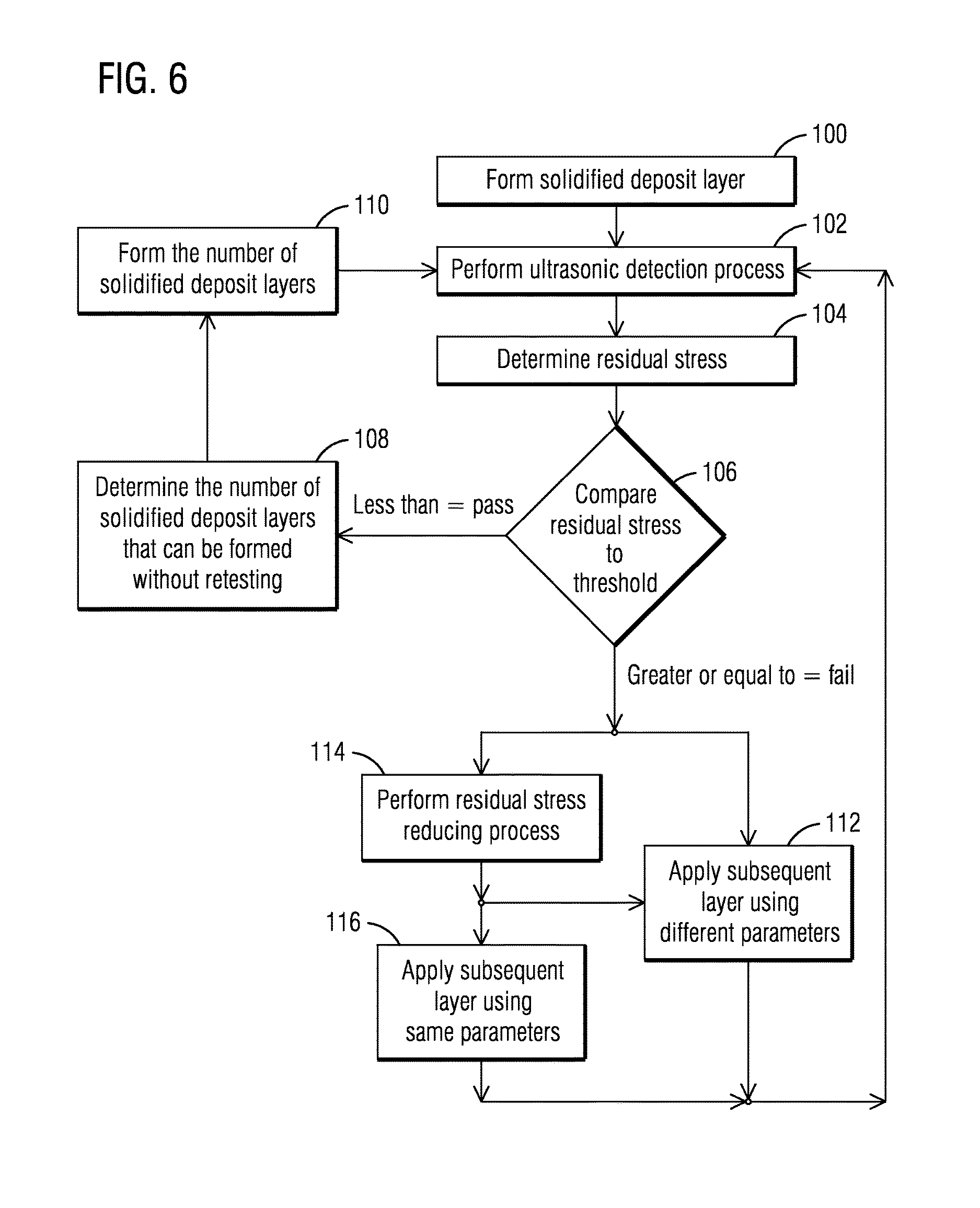
[0011]As with many manufacturing process, selective laser heating processes (e.g. SLM, SLS) result in physical characteristics, such as a defect and / or a buildup of residual stress. The level of residual stress can be high and can affect the structural integrity of the component. Consequently, it is beneficial to know the amount of residual stress present as well as any other defects. The inventors have recognized that residual stress may occur within each layer and may build up with the formation of additional layers, and that it will be beneficial to identify physical characteristics during the additive manufacturing process.

[0012]Prior techniques associated with residual stress control in, for example, building up of a blade tip, include alternating the application of the laser beam from side to side to even-out the residual stresses. These parts can then be heat treated to further alleviate the residual stresses. However, these processes do not necessarily measure the residual s...


PUM

PropertyMeasurementUnit
energyaaaaaaaaaa
physical characteristicaaaaaaaaaa
residual stressaaaaaaaaaa

Abstract

An additive manufacturing process, including: selectively-heating a layer of powder (18) to form a solid deposit layer (10) having a solid deposit (28), where the solid deposit layer constitutes part (24) of a component, via a selective laser heating process; propagating ultrasonic energy waves (50, 60) through the solid deposit prior to completion of the component by using a wave generating laser (40) set apart from a surface (44) of the solid deposit to direct a wave-generating laser beam (42) at the surface; detecting propagated ultrasonic energy waves (62); assessing the propagated ultrasonic waves for information about a physical characteristic of the solid deposit; and forming another solid deposit layer (80) in response to the information obtained about the solid deposit.

Description

FIELD OF THE INVENTION[0001]The present invention is related to in-situ, laser ultrasonic testing of a component that occurs between formation of layers in an additive manufacturing process.BACKGROUND OF THE INVENTION[0002]Additive manufacturing often starts by slicing a three dimensional representation of an object to be manufactured into very thin layers, thereby creating a two dimensional image of each layer. To form each layer, popular laser additive manufacturing techniques such as selective laser melting (SLM) and selective laser sintering (SLS) involve mechanical pre-placement of a thin layer of metal powder of precise thickness on a horizontal plane. Such pre-placement is achieved by using a mechanical wiper to sweep a uniform layer of the powder or to screed the layer, after which an energy beam, such as a laser, is indexed across the powder layer according to the two dimensional pattern of solid material for the respective layer. After the indexing operation is complete fo...

Claims


Application Information

Patent Timeline
Patent Type & Authority Applications(United States)
IPC IPC(8): G01N29/07B22F3/24B23K26/342G01L1/25C21D1/42C21D1/34C21D10/00B22F3/105C21D1/30
CPCG01N29/07G01N2291/011B22F3/24B23K26/342C21D1/30C21D1/42C21D1/34C21D10/005G01L1/255B33Y10/00B33Y50/02B22F2003/248B33Y40/00G01N2291/0289G01N2291/02827G01N2291/023B22F3/1055G01N21/1702B22F10/00B22F10/38B22F10/85B22F10/28B22F10/364B22F2998/10B22F10/50G01N29/043G01N2291/0231G01N2291/044B23K20/10B23K26/03B23K31/125C21D7/06B23K26/346Y02P10/25
Inventor KAMEL, AHMEDKULKARNI, ANAND A.
Owner SIEMENS ENERGY INC
Why Eureka
Try Eureka