Direct current power line communication control device using h-bridge circuit

Active Publication Date: 2017-04-20
TINYPOWERS
View PDF7 Cites 7 Cited by
  • Summary
  • Abstract
  • Description
  • Claims
  • Application Information

AI Technical Summary

Benefits of technology

The present invention provides a method for controlling power loads connected to an existing electric wire in a building, such as an ancient building. The method involves using RF communication or power line communication to control each load through the existing electric wire. This allows for easy installation and management, as well as reduced maintenance costs and improved aesthetic design. Additionally, the method distinguishes between different loads and allows for individual or group control, as well as diverse control options such as broadcasting control. This method is also more reliable and economical compared to other methods such as RF control modules or power line modems.

Problems solved by technology

However, high costs occur because various engrafted techniques are relatively complicated, it is vulnerable to noise because it uses weak signals, and there is an inconvenience to install a blocking filter or the like at the inlet stage to block the signals from being transmitted to an undesired portion through the power line.
The facts that economical communication based on a universally used general microcontroller is difficult, and that there is a problem in cost since a modem chip dedicated for communication has to be separately mounted are the main disadvantages.
If economic burden is rather larger than the case of separately installing a power line and a communication line, the value as a practical technique is low, and an alternative power line communication method which can be embodied with small and inexpensive components is necessary.
Since the waveform of a basic frequency has low frequency, if it does not pass through a process of smoothing power by applying an electrolytic capacitor with high capacity, flicker of LED lighting severely occurs.
In the case of long time use, which is identified as a main cause of the breakdown of an electrical product, it is difficult to avoid the problem of reducing the lifespan by deterioration according to disappearance of electrolyte in the electrolytic capacitor.
Particularly, since each LED lighting lamp or a power supply device for the lighting lamp installed on the ceiling is provided with an electrolytic capacitor component with high capacity which is a main cause of reduction of lifespan, the lifespan is short and maintenance is difficult.
Since a transformer or an inductor is used for converting alternating current power into low voltage actually used in an LED element, the volume becomes significantly large which makes it inconvenient to construct and manage.
Seeing the amount of power transmission, it is difficult to maintain low impedance of an ideal constant voltage source, so it is not suitable for the use of transmitting high power capable of driving a high-capacity load.
Since the voltage fluctuation according to transmission of a signal is severe, a capacitor with high capacity is necessary, and attention is required because it does not operate if connection of polarities is different at the time of installing a line.
In a case of direct current power transmission, a disadvantage of attention being required at the time of installation since it is necessary to distinguish polarities of + and −, and there is a practical problem that a situation in which mutual recognition is not achieved due to reverse phase even in a case of communication information may occur.

Method used


Image

  • Direct current power line communication control device using h-bridge circuit
  • Direct current power line communication control device using h-bridge circuit
  • Direct current power line communication control device using h-bridge circuit

Examples


Embodiment Construction

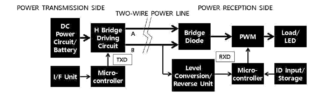
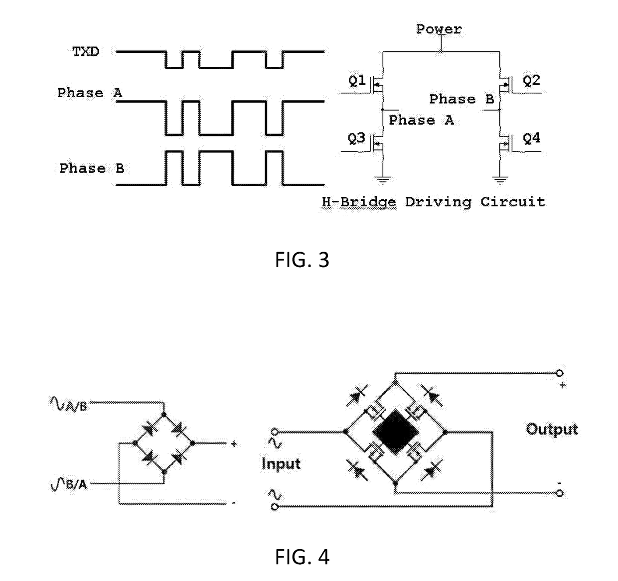
[0051]A plurality of loads are connected to an output of a direct current power supply device which is a direct current power supply source or an output terminal of a battery through electric wires in parallel, a transistor, a MOSFET, or an IGBT is provided at the output terminal of the battery or the direct current power supply device, and an H-bridge driving circuit capable of alternating polarities of (+) and (−) of the direct current power source output is connected. Change of relative values of magnitude of voltage of two power lines is referred to “polarity change” or “polarity fluctuation”. The H-bridge circuit changes polarities in accordance with data or information of a control command to be transmitted to a MICOM or an external signal, or outputs power of a change pattern of polarities according to time as mapped with digital values “0” and “1” in accordance with commitment in advance. In this case, it is driven to minimize cross over distribution.

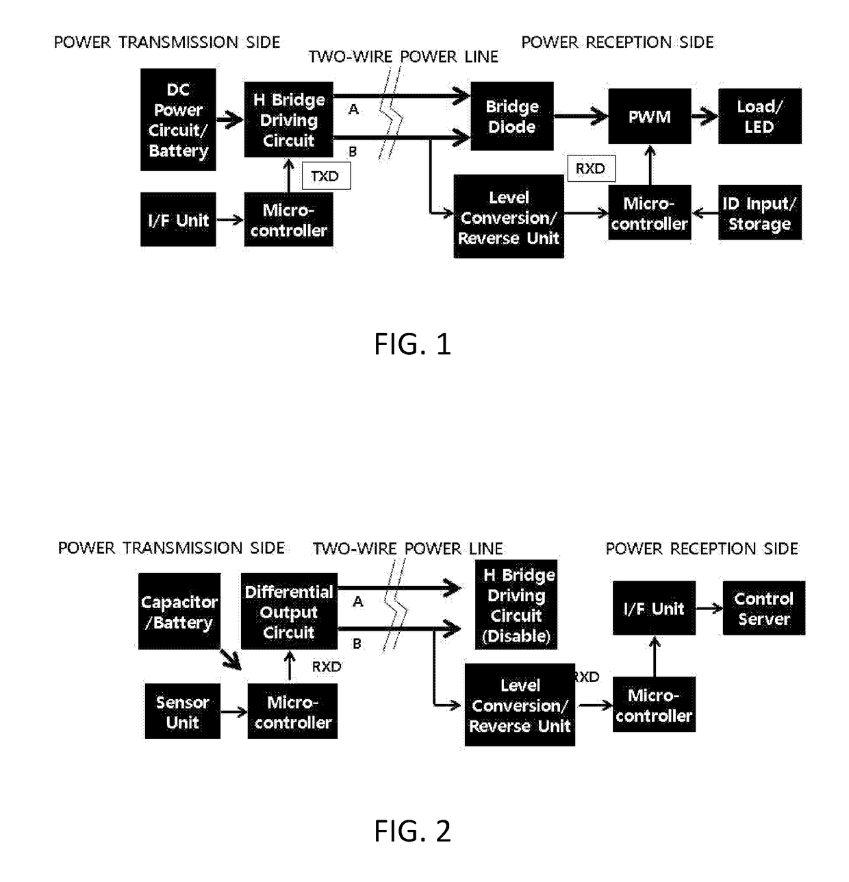
[0052]The reception side...


PUM


Abstract

Polarities of voltages on a plurality of electric wires are reversed with an H-bridge circuit applied in accordance with control information or data to be transmitted, information or data transmitted as change of polarities is found on the reception side, and the transmitted power is restored to direct current power through a bridge diode circuit and is used as power supplied to a load. Each load has a unique ID input and storage means, and the present invention is a communication method in which the unique ID is designated to the transmitted information or IDs are designated to groups to control a load. In addition, it is a method for spreading a PWM operation time to minimize noise generated in accordance with PWM driving on the reception side, In a direct current transmission and reception environment, data or a command signal for power demand response is mapped with the polarity of voltage and is transmitted to each customer, and it may be applied to the power demand response technique.

Description

TECHNICAL FIELD[0001]The present invention relates to a method for transmitting power of a direct current power source and simultaneously transmitting data or control information through one line. In a case of an LED lighting field, which is one of the embodiments of the present invention, the final power use type is direct current power, so the direct current power and control information are transmitted through the same line by using the existing installed line for lighting as it is, making it possible to transmit the control information for adjusting brightness or color of each LED lighting lamp connected to a lighting line, and to control each LED in accordance with reception control information in various reception side LED lighting lamps connected in parallel.[0002]When a battery is used basically, such as in vehicles, each load in a vehicle uses direct current power, and it is useful even for a case of transmitting power and control information to each load. The present inven...

Claims


Application Information

Patent Timeline
IPC IPC(8): H04B3/54H02J13/00
CPCH02J13/0089H04B3/54G08C19/02H04B3/548H05B47/185H05B45/20H05B45/46H05B47/165Y02B20/30
Inventor CHOI, CHANGJOONCHOI, JAEBOO
Owner TINYPOWERS
Why Eureka
Try Eureka