Ignition control and system for an engine of an unmanned aerial vehicle (UAV)

a technology for unmanned aerial vehicles and ignition control systems, which is applied in the direction of electric control, ignition automatic control, machines/engines, etc., can solve the problems of increased engine failure risk, complete loss of uav, and uav crash, and achieve optimal combustion and sufficient power

Active Publication Date: 2017-05-04
ORBITAL ENGINE CO PTY LTD
View PDF1 Cites 5 Cited by
  • Summary
  • Abstract
  • Description
  • Claims
  • Application Information

AI Technical Summary

Benefits of technology

[0058]Modification of the secondary ignition spark timing can achieve more optimal combustion than leaving the secondary ignition spark timing at a timing position prevailing prior to the primary ignition system failing.
[0059]As introduced above, the secondary ignition system may provide sufficient spark energy to maintain the engine running in a ‘limp home’ mode of operation. In a limp home mode, the engine has sufficient power and ability to keep running under moderate loads to get the UAV back to base or point of origin, but typically not to operate under very high RPM, high loads or extreme lean fuel-air mixture conditions. Consequently, preferably a simplified ignition strategy and fuel-air mixture strategy may be employed. The fuel-air mixture may be maintained within a rich to stoichiometric range, or preferably have excursions into just weak of stoichiometric for periods of operation.

Problems solved by technology

Minimising components in the ignition system, particularly where this may impact on any redundancy capability, can however lead to an increased risk of engine failure, and ultimately potentially complete loss of the UAV.
UAVs need to be reliable because the consequences of mechanical or electrical failure (such as engine mechanical failure or engine sub-system failure e.g. the ignition system) can be very severe.
If a UAV in some way fails whilst flying, it comes down to earth very quickly, often with catastrophic results in terms of the UAV crashing.
Also, such failure can happen when the UAV is a long way from its base and potentially over dangerous or difficult terrain, making safe recovery risky or impossible.
There is also the associated risk of losing very expensive surveillance or other equipment carried by the UAV.
However, this tends to lead directly to increased UAV weight.
Furthermore, in terms of reliability, having only one ignition system on-board does not allow for any failure at all of the ignition system.
This may not satisfy certain regulatory requirements for such aerial vehicles when used in specific applications.
However, merely duplicating the primary ignition system can significantly impact desired weight (and often size) constraints of the UAV which can drastically reduce performance and range of the UAV.
Adding a second inductive coil to provide redundancy capability for the ignition system of a UAV would hence add significant weight to the UAV.
Also, duplicating the primary ignition system significantly invariably adds to the cost of the UAV ignition system, not least because the primary ignition system components needing to be robust are therefore relatively expensive.
Whilst it would be beneficial to have full ignition system redundancy with two matching (duplicated) ignition systems for a heavy fuel UAV engine, the added weight of the complete second system would be too detrimental to performance and the effect on cost would also be an issue.
An ignition system along these lines which includes two standard ignition systems, one serving as a primary system, and one for backup / redundancy purposes, would make for an uncompetitive overall engine package.
However, duplication of parts is in conflict with the requirement to keep weight to a minimum.

Method used


Image

  • Ignition control and system for an engine of an unmanned aerial vehicle (UAV)
  • Ignition control and system for an engine of an unmanned aerial vehicle (UAV)
  • Ignition control and system for an engine of an unmanned aerial vehicle (UAV)

Examples


Embodiment Construction

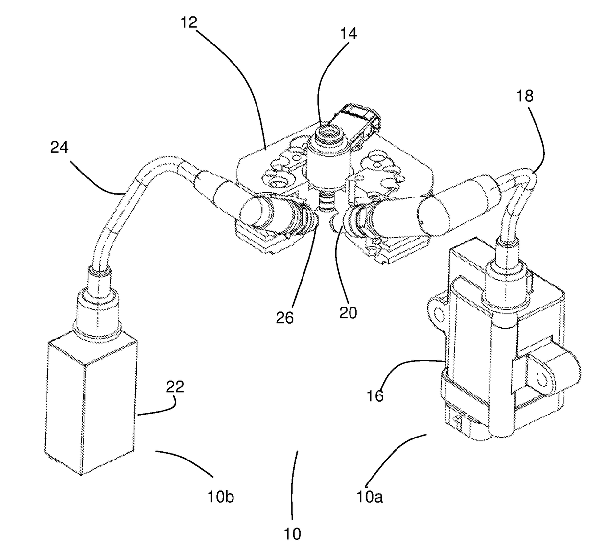
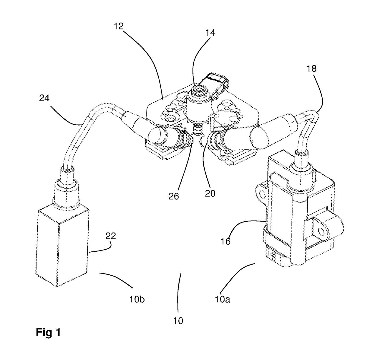
[0076]FIG. 1 shows an embodiment of an ignition system 10 of the present invention.

[0077]A cylinder head 12 of a UAV engine has mounted to it a delivery injector 14 and two spark plugs 20, 26.

[0078]The ignition system 10 includes primary 10a and secondary 10b ignition systems.

[0079]The primary ignition system 10a includes a primary ignition unit 16 electrically connected via a high tension (HT) lead 18 to one of the two spark plugs 20.

[0080]The primary ignition unit 16 converts low voltage (low tension) pulses to high voltage (HT) pulses. The HT pulses result in primary sparking at the respective spark plug 20.

[0081]The primary ignition unit 16 includes an inductive coil having an iron core. Such inductive coils are reliable and produce high power sparking over a short period of time.

[0082]The secondary ignition system 10b includes a secondary ignition unit 22 connected via a second high tension lead 24 to the second spark plug 26.

[0083]In the embodiment described the secondary igni...


PUM


Abstract

The ignition system (10) of an engine (particularly for a UAV) has a primary (10a), and a secondary (10b) ignition system to provide redundancy for ‘get you home’ capability should the primary ignition system fail. The secondary ignition provides a lower energy or shorter duration spark than the higher energy or longer duration sparking of the primary ignition system, and is retarded relative to primary sparking. Timing of the secondary sparking can be advanced in the event of primary sparking failure. Fuelling strategy can be shifted from a leaner stratified charge to a richer homogenous charge when relying just on the secondary ignition system for ignition. The secondary ignition system can be of a lower spark energy and/or duration than the primary ignition system, avoiding the cost, complexity and weight of replicating the primary ignition system, and to improve packaging within the engine housing, particularly within the limited payload and space limits of a UAV.

Description

FIELD OF THE INVENTION[0001]The present invention relates to ignition control and ignition systems for engines used in unmanned aerial vehicles.[0002]The present invention is particularly applicable to redundancy in ignition control and ignition systems for UAV engines using heavy fuels.BACKGROUND TO THE INVENTION[0003]Unmanned aerial vehicles (UAVs) require range and durability in the air. To help achieve this, engines and their control systems need to be relatively light in weight and yet provide high performance.[0004]One way to achieve lightness in weight is to omit as many non-essential components and control systems as possible and / or make such components lightweight. However, to survive in the extreme ambient conditions that UAVs are exposed to, the engine and its control systems also need to be robust and reliable.[0005]The ignition system is one essential engine control system. Without an ignition system the UAV engine will not start or continue to run.[0006]Minimising comp...

Claims


Application Information

Patent Timeline
Patent Type & Authority Applications(United States)
IPC IPC(8): F02P15/02F02P17/00F02P5/15F02P9/00F02P3/04F02P3/08
CPCF02P15/02F02P3/0407F02P17/00F02P5/1502F02P9/007F02P3/0807F02D2041/227F02D2400/08F02P15/08F02C7/266Y02T10/40
Inventor CATHCART, GOEFFREY PAULBUTERS, NICOLASS HARRY
Owner ORBITAL ENGINE CO PTY LTD
Why Eureka
Try Eureka