
Large-area detector apparatus for photosensor, radiation detector, and medical pet scanner applications

a radiation detector and large-area technology, applied in the field of photosensors, can solve the problems of reducing the detection efficiency of gamma-ray pairs, requiring the patient to be exposed to high radioactive doses, and generating noise, so as to reduce the cost and complexity, and increase the sensitivity

Active Publication Date: 2017-05-04
RGT UNIV OF CALIFORNIA
View PDF3 Cites 4 Cited by
  • Summary
  • Abstract
  • Description
  • Claims
  • Application Information

AI Technical Summary

Benefits of technology

The patent discloses a new way to detect photo-radiation, particularly with a full body PET scanner that can enclose the human body and perform a whole-body scan in a single step. This approach increases sensitivity and reduces the amount of harmful radiation required, ultimately reducing the duration of the examination and the dosage of radiation given to the patient. This new technology is referred to as an ABALONE-PET scanner.

Problems solved by technology

Operating these conventional systems requires the patient to be exposed to high radioactive doses.
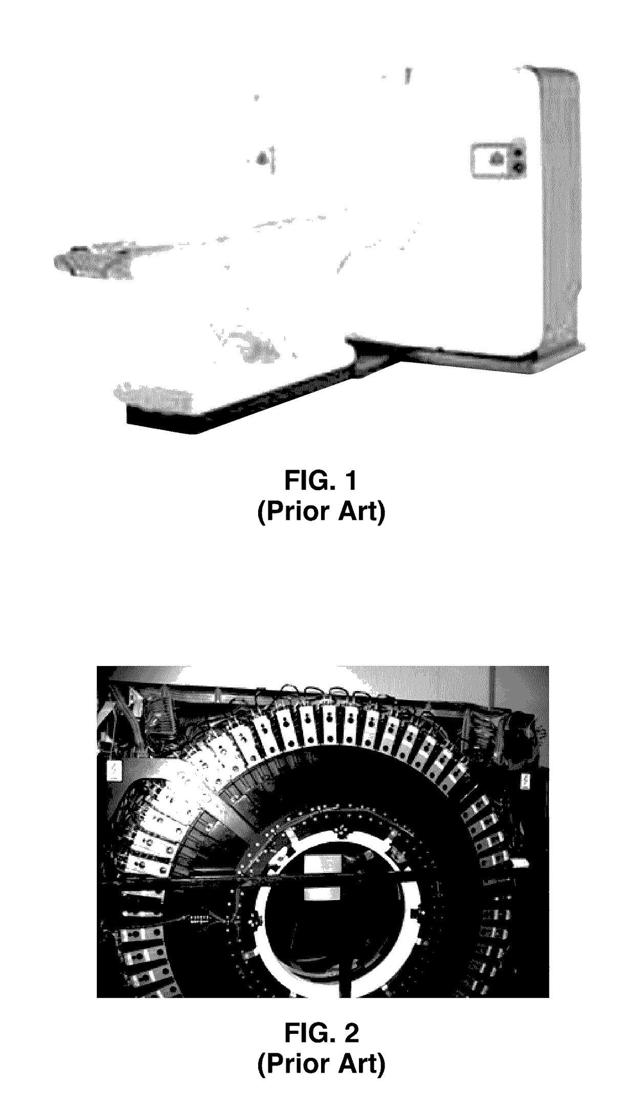
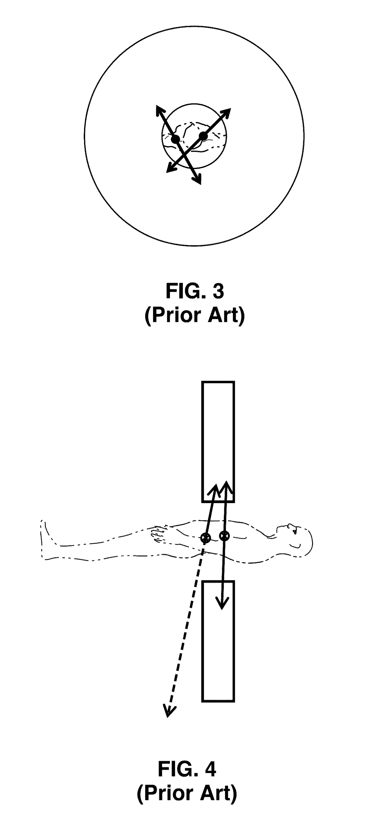
In particular, many of the positron annihilation events occurring within the ring-PET proximity are lost to detection because one of the gamma rays escapes.
In FIG. 5 it is seen that the loss of Gamma-ray pairs not only leads to lowered signal levels, but also to the generation of noise.
Accidental coincidences of gamma rays originating at all parts of a patient's body create high-level of background coincidence noise.

Method used


Image

  • Large-area detector apparatus for photosensor, radiation detector, and medical pet scanner applications
  • Large-area detector apparatus for photosensor, radiation detector, and medical pet scanner applications
  • Large-area detector apparatus for photosensor, radiation detector, and medical pet scanner applications

Examples


embodiment 10

[0049]FIG. 7 and FIG. 8 depict a comparison of parallax error in a large-diameter PET scanner like ABALONE PET, compared with the hypothetical use of a plurality of ring detection sections. In the ABALONE embodiment 10 of FIG. 7, the gamma-ray detector envelope 14 curves not only around the longitudinal axis of the patient as in a ring-detector, but also curves around the transverse axis of the patient's body 12. Thus, both gamma rays 16a, 16b in the gamma ray pair originating in the patient at locations 18a, 18b are detected in the system with only minor parallax error due to the three dimensional curving within the ABALONE PET scanner.

[0050]A conventional ring-PET was already described in FIG. 3 through FIG. 6, in which only a small portion of the gamma rays are detected. In FIG. 8 we see a hypothetical PET configuration 30 built up from a number of ring PETs 36a through 36n. A patient 32 is seen with an example gamma ray pair 34a, 34b which extends out striking the different stac...

embodiment 50

[0057]FIG. 9A through FIG. 9C depict an ABALONE photon detector, which is shown in an embodiment 50 for use with the ABALONE PET of the present disclosure. The cross section of FIG. 9A depicts the entire ABALONE photon detector 50, with a transparent upper housing 52 seen in FIG. 9B, and the electron detector 54 itself seen in FIG. 9C.

[0058]In FIG. 9A a photon detector embodiment 50 is exemplified with housing 52 seen with an outer sensor hemisphere 53 and photocathode 64, connected to a base plate 56, with ramped area 58 leading to an aperture 60 centered upon which is seen a seal 62, covered with the electron detector comprising a scintillator layer retained beneath the vacuum enclosure, and a photodetector 54 optically coupled to the underlying windowlet on the atmospheric side (e.g., a Geiger-Mode Avalanche Photodiode).

[0059]In FIG. 9B an embodiment of the photon detector housing 52 comprises a single molded dome piece of dielectric light-transmissive material (e.g., glass) havi...


PUM


Abstract

A large area position-sensitive single-photon detector and radiation detector is described. Photon detectors are coupled to a large area panel configured with an equipotential feedthrough chamber that operates in combination with a photocathode of a hemispherical window to provide electrostatic focusing for the photoelectrons. The panels can be assembled into an enveloping structure, such as a PET scanner, which is globally and / or locally curved, such as into a sphere, ovoid, elongated cylinder, or similar structure providing significant sensitive surface surrounding an object, such as a patient being scanned in a medical positron emission tomography (PET) scanner. Increased sensitivity is provided in response to registering radiation by surrounding the patient, so that reduced patient radiation dosing levels are required.

Description

CROSS-REFERENCE TO RELATED APPLICATIONS[0001]This application is a 35 U.S.C. §111(a) continuation of PCT international application number PCT / US2015 / 031188 filed on May 15, 2015, incorporated herein by reference in its entirety, which claims priority to, and the benefit of, U.S. provisional patent application Ser. No. 61 / 993,906 filed May 15, 2014, incorporated herein by reference in its entirety. Priority is claimed to each of the foregoing applications.[0002]The above-referenced PCT international application was published as PCT International Publication No. WO 2015 / 176000 on Nov. 19, 2015, which publication is incorporated herein by reference in its entirety.STATEMENT REGARDING FEDERALLY SPONSORED RESEARCH OR DEVELOPMENT[0003]Not ApplicableINCORPORATION-BY-REFERENCE OF COMPUTER PROGRAM APPENDIX[0004]Not ApplicableNOTICE OF MATERIAL SUBJECT TO COPYRIGHT PROTECTION[0005]A portion of the material in this patent document is subject to copyright protection under the copyright laws of ...

Claims


Application Information

Patent Timeline
Patent Type & Authority Applications(United States)
IPC IPC(8): G01T1/29
CPCG01T1/2985A61B6/037G01T1/20188
Inventor FERENC, DANIEL
Owner RGT UNIV OF CALIFORNIA
Learn More