
Developing member, method of producing the same, process cartridge and electrophotographic image forming apparatus

a technology of developing members and electrophotographic images, which is applied in the direction of electrographic process, electrographic process apparatus, instruments, etc., can solve the problems of reducing the mobility of ionic conductive agents, and achieve the effect of ensuring electro-conductivity

Inactive Publication Date: 2017-05-18
CANON KK
View PDF3 Cites 15 Cited by
  • Summary
  • Abstract
  • Description
  • Claims
  • Application Information

AI Technical Summary

Benefits of technology

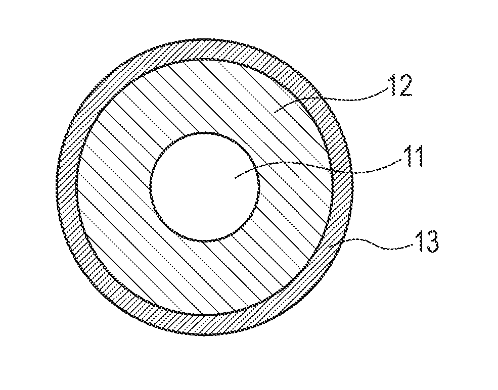
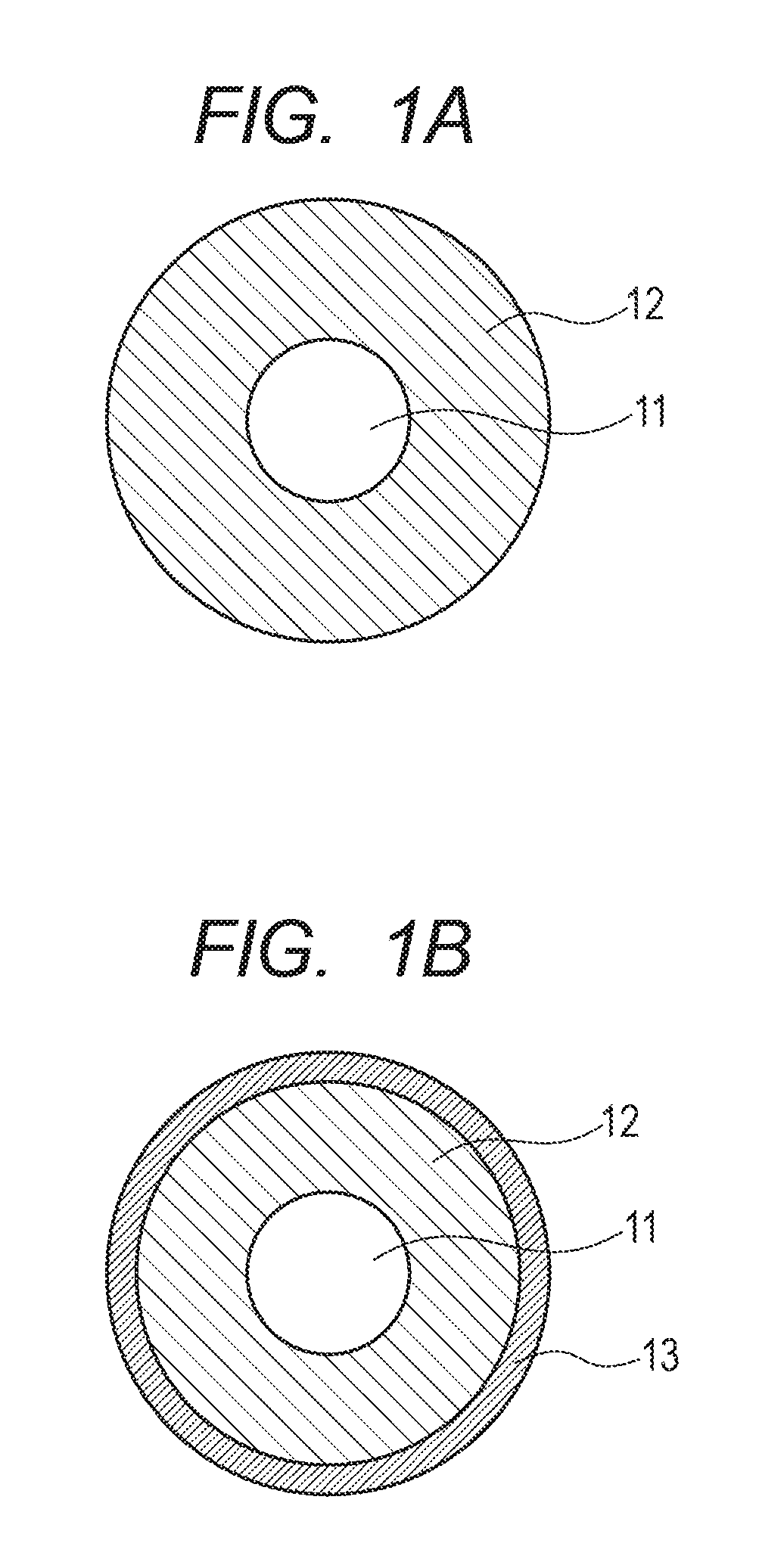
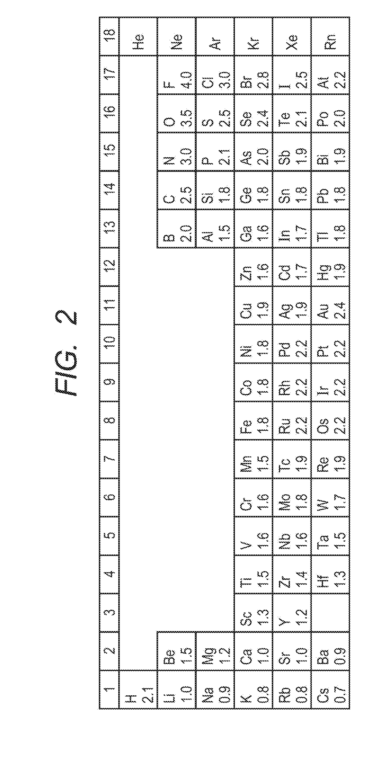
The present invention provides a developing member with an elastic layer containing a metal oxide with electronegativity of (11.0 or less, which exhibits electro-conductivity under low temperature and low humidity environments and prevents a reduction in durability of the developing member. The elastic layer can contain a compounding agent, a non-electro-conductive filler, a crosslinking agent, and a catalyst when necessary. Additionally, a particle for controlling roughness can be added in the elastic layer to achieve the desired surface roughness. The technical effect of the invention is to provide a developing member with enhanced durability and performance under various environments.

Problems solved by technology

Unfortunately, in such an ionic conductive agent having a cation fixed inside the resin and an anion having a large molecular weight to prevent the bleed, adverse effects which may be caused by reduced mobility of the ionic conductive agent have been found in some cases in the examination under low temperature and low humidity (such as a temperature of 10° C. and a relative humidity of 10%) environments where the molecular mobility reduces.

Method used


Image

  • Developing member, method of producing the same, process cartridge and electrophotographic image forming apparatus
  • Developing member, method of producing the same, process cartridge and electrophotographic image forming apparatus
  • Developing member, method of producing the same, process cartridge and electrophotographic image forming apparatus

Examples


example 1

[0143][1. Preparation of Elastic Roller]

[0144]A primer (tradename, DY35-051; made by Dow Corning Toray Co., Ltd.) was applied to an SUS304 (JIS, stainless steel) electro-conductive substrate having a diameter of 6 mm and a length of 270.5 mm. The workpiece was heat treated in an oven heated to a temperature of 180° C. for 20 minutes to prepare an electro-conductive substrate. The electro-conductive substrate was placed in a metal mold, and an addition silicone rubber composition including a mixture of the materials shown in Table 8 below was injected into the cavity formed in the metal mold. Silica powder was used as a heat resistance imparting agent.

TABLE 8Parts byMaterialsmassLiquid silicone rubber material100(Trade name, SE6724A / B; made byDow Corning Toray Co., Ltd.)Carbon black15(Trade name, TOKABLACK#4300;made by TOKAI CARBON CO., LTD.)Silica powder0.2Platinum catalyst0.1

[0145]The metal mold was then heated at 150° C. for 15 minutes to vulcanize and cure silicone rubber. A cure...

examples 2 to 49

[0198]Developing members 2 to 49 were prepared by the same method as in Example 1 except that the types and the amounts of the ionic conductive agent and the metal oxide added were varied as shown in Table 10. The results of evaluation are shown in Table 10.

TABLE 10Ionic conductiveagentMetal oxideEvaluationAmountAmountChargeofTypeaddedTypeElectronegativityaddedBleedDeformationupImageDurabilityExample 1 1-31A6.030ABAAAExample 21-31B8.030ABAAAExample 31-31E10.530ABBBAExample 41-41A6.030AAAAAExample 51-41B8.030AAAAAExample 61-41E10.530AABBAExample 71-41F10.530AAAAAExample 81-41D10.530AABBAExample 91-41C10.530AABBBExample 101-41E10.50.5AACCAExample 111-41E10.51AABBAExample 121-41E10.575AAAABExample 131-41E10.5100AAAACExample 141-430E10.530BAAAAExample 151-420E10.530BAAAAExample 161-40.01E10.530AAAAAExample 171-40.001E10.530AACCAExample 181-21A6.030BBAAAExample 191-21B8.030BBAAAExample 201-21E10.530BBBBAExample 211-51A6.030AAAAAExample 221-51E10.530AABBAExample 231-61A6.030AAAAAExample 2...

example 50

[0199]The materials for an elastic layer shown in the column of Component (1) of Table 11 below were mixed with stirring by a stirring motor for one hour to provide a mixed solution. Subsequently, other materials shown in the column of Component (2) of Table 11 were added to the mixed solution (solid content: 100 parts by mass) to prepare Mixed solution 2′. Crosslinked urethane beads were used as roughening particles. Except for these, Developing member 50 was prepared, and evaluated in the same manner as in Example 1. The results of evaluation are shown in Table 10.

TABLE 11Parts byMaterialsmassComponentTerephthalic acid (made by Tokyo100(1)Chemical Industry Co.,Ltd.)Methyl ethyl ketone (MEK)500ComponentSolid content of Component (1)100(2)Ionic conductive agent 1-420Metal oxide A30Crosslinked urethane beads (Trade20name: C-400 Transparent; made byNegami chemical industrial co., ltd.)


PUM

PropertyMeasurementUnit
humidityaaaaaaaaaa
temperatureaaaaaaaaaa
electro-conductiveaaaaaaaaaa

Abstract

A developing member that can prevent bleed under a high temperature and high humidity and prevent charge up of the developing member under a low temperature and low humidity is provided. A developing member including an electro-conductive substrate and an elastic layer disposed on the electro-conductive substrate; the elastic layer including a binder resin, an anion and a particle containing a metal, oxide; the binder resin including a resin having a cationic organic group in the polymer chain; the anion being at least one selected from the group consisting of a fluorinated sulfonate anion, a fluorinated carboxylate anion, a fluorinated sulfonylimide anion, a fluorinated sulfonylmethide anion, a dicyanamide anion, a fluorinated alkylfluoroborate anion, a fluorinated phosphate anion, a fluorinated antimonate anion, a fluorinated arsenate anion and a bis(oxalate)borate anion; the metal oxide including an oxide of a metal having an electronegativity of 11.0 or less as a metal ion.

Description

BACKGROUND OF THE INVENTION[0001]Field of the Invention[0002]The present disclosure relates to developing members used in electrophotographic image forming apparatuses, methods of producing the same, process cartridges and electrophotographic image forming apparatuses.[0003]Description of the Related Art[0004]In electrophotographic image forming apparatuses operated by a non-magnetic one-component developing method, the developing member feeds a toner and charges the toner at the same time. The desired properties of the developing member include characteristic values such as appropriate hardness and electric resistance. The developing member is often composed of an elastic body to achieve such hardness. Furthermore, the developing member contains an ionic conductive agent such as quaternary ammonium salts to impart electro-conductivity to the elastic body. Since the ionic conductive agent in the elastic layer is homogeneously present in the molecular level, in comparison to electron...

Claims


Application Information

Patent Timeline
Patent Type & Authority Applications(United States)
IPC IPC(8): G03G15/08
CPCG03G9/087G03G9/0802G03G21/18G03G15/0233G03G15/0818C08L75/08C08K5/16G03G21/1814
Inventor NAGAOKA, KAZUAKINAKAMURA, MINORUMIYAUCHI, YUTOYAMAGUCHI, SOSUKE
Owner CANON KK
Learn More