

Systems and methods for implementing three dimensional (3D) object, part and component manufacture including locally laser welded laminates
a technology of three-dimensional objects and local laser welding, which is applied in the field of system and method for implementing three-dimensional objects, part and component manufacture including locally laser welded laminates, can solve the problems of limiting the build speed of 3d objects in the conventional am manufacturing process, difficult to achieve typical material deposition techniques, and difficult to achieve the effect of reducing, or substantially eliminating, the requirement for additional support structure materials
- Summary
- Abstract
- Description
- Claims
- Application Information
AI Technical Summary
Benefits of technology
Problems solved by technology
Method used
Image

Examples
Embodiment Construction
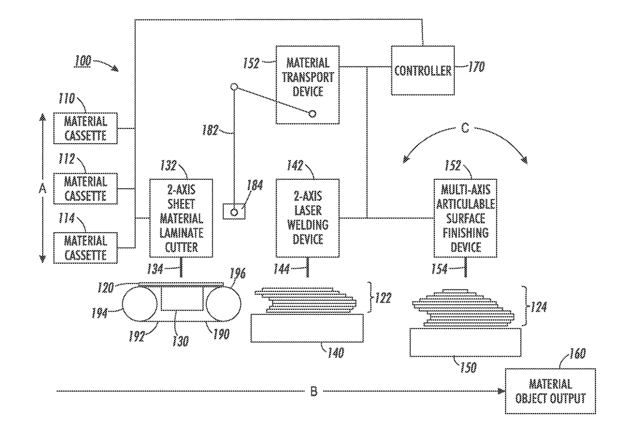
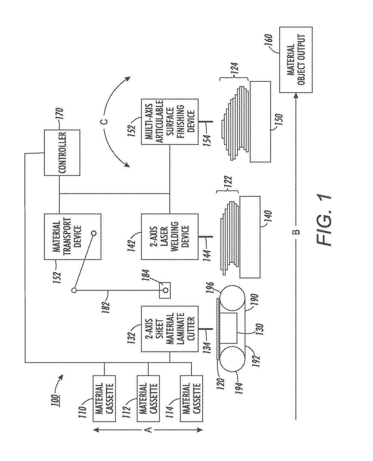
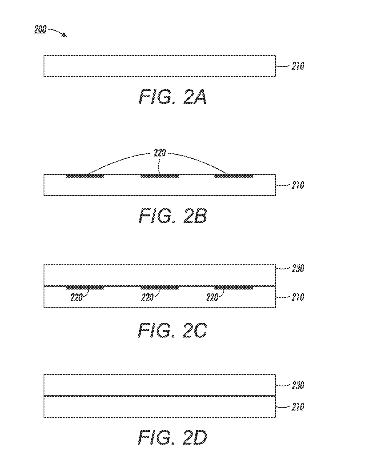
[0003]This disclosure relates to systems and methods for implementing localized and directed laser welding joining techniques in a process of building up laminate layers to form and / or manufacture three-dimensional objects, parts and components (3D objects).
[0004]2. Related Art
[0005]In recent years, traditional object, part and component manufacturing processes, which generally included varying forms of molding or machining of output products, have expanded to include a new class of techniques globally referred to as “additive material” or AM manufacturing techniques. These techniques, as currently implemented, generally involve processes in which layers of additive material, sometimes toxic or otherwise hazardous in an unfinished state, are sequentially deposited on the in-process 3D object according to a particular material deposition and curing scheme. As each layer is added in the 3D object forming process, the new layer of deposited material is added and adhered to the one or m...
PUM
| Property | Measurement | Unit |
|---|---|---|
| fused deposition modelling | aaaaa | aaaaa |
| energy | aaaaa | aaaaa |
| thermoplastic | aaaaa | aaaaa |
Abstract
Description
Claims
Application Information