
Electrically conductive adhesives, assemblies including the electrically conductive adhesives, and related methods

a technology adhesives, applied in the field of electrically conductive adhesives, can solve the problems of exhaust plumes, space vehicles such as space shuttles, rockets, satellites, etc., to be exposed to hostile conditions characterized by high temperatures and turbulence, and to be exposed to extreme temperatures

Active Publication Date: 2017-05-25
NORTHROP GRUMMAN SYST CORP
View PDF3 Cites 3 Cited by
  • Summary
  • Abstract
  • Description
  • Claims
  • Application Information

AI Technical Summary

Benefits of technology

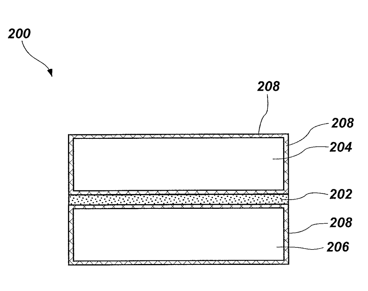
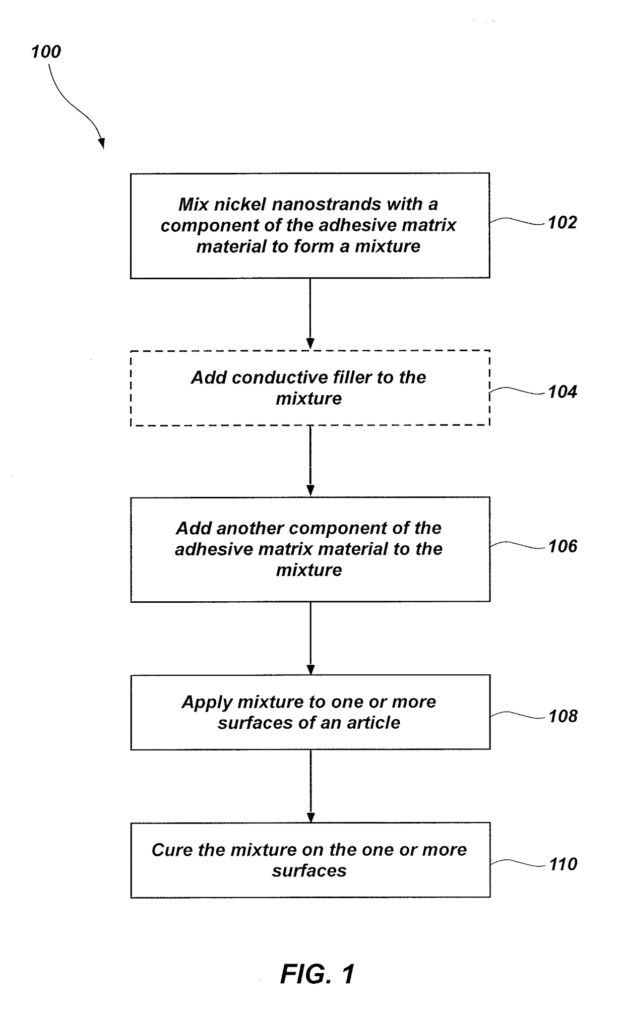
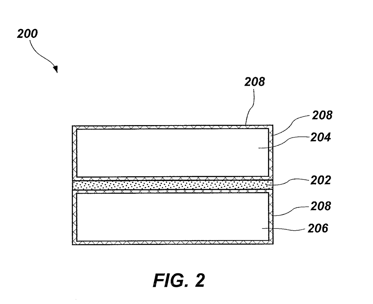
Embodiments of this patent describe electrically conductive adhesives made of nickel nanostrands dispersed in a matrix of epoxy resin and curing agents. These adhesives have a high adhesion strength and low resistivity, making them suitable for use in electrical interconnections. The patent also describes a method for forming an assembly by using the electrically conductive adhesive between two articles. A precursor package for the adhesive is also described. The technical effects of this patent are improved electrical interconnections and more reliable adhesion between the two articles.

Problems solved by technology

Space vehicles, such as space shuttles, rockets, satellites, missiles, etc., may be exposed to hostile conditions characterized by high temperatures and turbulence during flight (e.g., launch, ascent, re-entry, etc.).
For example, a space vehicle may be exposed to extreme temperatures such as exhaust plumes, heat generated by atmospheric friction during launch and re-entry, etc.
Excessive heat may damage one or more portions of the space vehicle, including, for example, wings, nozzles, a nose cone, fuel tanks, engine exhaust ducts, re-entry shield surfaces, etc.
In addition, charges may build up on surfaces of the space vehicle over time (such as by triboelectrification), eventually resulting in ESD.
However, some foils may be expensive and prone to mechanical failure.
Further, high currents from lightning strikes or ESD may damage sites of electrical discontinuity where the current may arc, such as at locations between composite panels, mechanical fasteners, joints, fiber interfaces, etc.
However, the large volume of silver required for sufficient electrical conductivity reduces an adhesion strength of the adhesive and, thus, materials adjoined by the adhesive may debond in the event of a lightning strike or ESD.
Further, the large volume of silver may also be cost prohibitive in many applications.

Method used


Image

  • Electrically conductive adhesives, assemblies including the electrically conductive adhesives, and related methods
  • Electrically conductive adhesives, assemblies including the electrically conductive adhesives, and related methods
  • Electrically conductive adhesives, assemblies including the electrically conductive adhesives, and related methods

Examples


example 1

[0070]Electrically conductive adhesives formulated according to the methods described herein were tested against conventional electrically conductive adhesives in lightning strike tests. An electrically conductive adhesive including about 70 parts by weight bisphenol-F epoxy resin, 30 parts by weight resorcinol diglycidyl ether monomer, about 5 parts by weight Accelerator® 399 curing promoter, about 31 parts by weight Jeffamine® D230, about 15.5 parts by weight Jeffamine® D400, and about 216 parts by weight nickel nanostrands was formed.

[0071]The electrically conductive adhesive including nickel nanostrands was placed between a carbon composite panel and a metallic fastener (e.g., an aluminum end ring), such as would be used to couple adjacent composite panels of, for example, a cylindrical rocket case. The panel was subjected to a simulated direct lightning strike. Commercially available electrically conductive adhesives were also disposed between carbon composite panels and a meta...

example 2

[0073]An adhesion strength of the electrically conductive adhesive including nickel nanostrands was compared to an adhesion strength of commercially available electrically conductive adhesives. The adhesion strength was measured using a tensile butt test, wherein the electrically conductive adhesive was disposed between two composite materials that were pulled apart at a rate of about 0.5 inch per minute (ipm) until the electrically conductive adhesive between the composite materials failed. The bond line in each case was about 7 mils.

[0074]The electrically conductive adhesive including the nickel nanostrands exhibited a substantially greater tensile adhesion strength than conventional electrically conductive adhesives, while also exhibiting an electrical resistivity lower than the conventional electrically conductive adhesives, as illustrated in Table I below. The electrically conductive adhesive with the nickel nanostrands had the same composition of the electrically conductive ad...

example 3

[0075]A tensile strength and an electrical resistivity of different formulations of the electrically conductive adhesive including nickel nanostrands were measured at a bond line thickness of about 30 mils. In some embodiment, the electrically conductive adhesive further included an additional conductive co-filler (electrically conductive silver microspheres) dispersed therein. The test results are reproduced in Table II below, wherein percents are in volume percent of the resulting electrically conductive adhesive. The adhesive matrix material was a urethane in formulations 1 through 4 and the adhesive matrix material was an epoxy in formulations 5 through 12. The composition of formulations 1 through 4 are reproduced in Table III and the composition of formulations 5 through 12 are reproduced in Table IV below:

TABLE IINickelElectricalTAFormulationNanostrandsCo-fillerResistivityStrength12%15%0.1562 Ω· cm 208 psi26%15%0.1072 Ω· cm 261 psi310%15%0.0184 Ω· cm 281 psi415%15%0.0453 Ω· c...


PUM

PropertyMeasurementUnit
Fractionaaaaaaaaaa
Fractionaaaaaaaaaa
Percent by massaaaaaaaaaa

Abstract

An assembly comprising a first article, a second article adjacent the first article, and an electrically conductive adhesive in electrical communication with the first article and the second article. The electrically conductive adhesive comprises nickel nanostrands dispersed in a matrix comprising a reaction product of bisphenol-F epoxy resin, resorcinol diglycidyl ether epoxy monomer, and at least one amine-containing curing agent. The electrically conductive adhesive exhibits a tensile adhesion strength greater than about 5,000 psi and a volume resistivity less than about 0.01 Ω·cm. Electrically conductive adhesives including nickel nanostrands, precursor packages of the electrically conductive adhesive, related methods of forming the electrically conductive adhesive and an assembly including the electrically conductive adhesive are also disclosed.

Description

TECHNICAL FIELD[0001]Embodiments of the disclosure relate generally to electrically conductive adhesives including nickel nanostrands, assemblies such as space vehicles including the electrically conductive adhesives, and to related methods.BACKGROUND[0002]Space vehicles, such as space shuttles, rockets, satellites, missiles, etc., may be exposed to hostile conditions characterized by high temperatures and turbulence during flight (e.g., launch, ascent, re-entry, etc.). Such space vehicles are formed of multiple components secured together or in adjacent relationship, and may require both thermal protection systems and electrical protection systems to protect the space vehicle from damage that may be caused during flight.[0003]For example, a space vehicle may be exposed to extreme temperatures such as exhaust plumes, heat generated by atmospheric friction during launch and re-entry, etc. Excessive heat may damage one or more portions of the space vehicle, including, for example, win...

Claims


Application Information

Patent Timeline
IPC IPC(8): C09J9/02B32B37/12C09J163/00B32B7/12H05K1/02C09J5/00B32B7/08
CPCC09J9/02H05K1/0296C09J5/00C09J163/00B32B7/12B32B37/12B32B2605/18B32B2250/02B32B2255/26B32B2307/304B32B2307/202B32B2457/00C09J2463/00B32B5/022B32B5/26B32B7/08B32B9/041B32B9/045B32B9/047B32B15/02B32B15/043B32B15/09B32B15/092B32B15/098B32B18/00B32B27/08B32B27/12B32B27/36B32B27/38B32B27/42B32B3/04B32B2250/05B32B2262/103B32B2307/20B32B2307/206B32B2307/54B32B2307/72B32B2307/732B32B2605/00B32B2307/212C08K7/06C08K2003/0862C08K2201/001
Inventor LARSON, ROBERT S.
Owner NORTHROP GRUMMAN SYST CORP
Learn More