Turbo chiller

a chiller and rotating shaft technology, applied in the field of rotating shaft chillers, can solve the problems of unavoidable maintenance such as changing the lubricating oil and the oil filter, and achieve the effects of reducing the loss of rolling bearing bearings, reducing power loss, and increasing rotation

Inactive Publication Date: 2017-05-25
MITSUBISHI HEAVY IND THERMAL SYST
View PDF4 Cites 28 Cited by
  • Summary
  • Abstract
  • Description
  • Claims
  • Application Information

AI Technical Summary

Benefits of technology

[0020]According to the present invention, power loss at the speed-increasing gear unit and bearing losses of rolling bearings are reduced, allowing the turbo compressor to have higher rotation suitable for high flow rate refrigerant compression, thus compensating for inherent problems with using the R1233zd(E) refrigerant, which has been considered to have difficulties involved in ensuring suitable performance due to the low density of the low-pressure refrigerant and its high sonic velocity compared to conventional HFC refrigerants. Additionally, by having an oil-free configuration without a speed-increasing gear unit or rolling bearings that require oil lubrication and usi

Problems solved by technology

While this is not in violation of regulations, it is undesirable from the perspective of global warm

Method used


Image

  • Turbo chiller
  • Turbo chiller
  • Turbo chiller

Examples


first embodiment

[0026]A first embodiment of the present invention will be described below, using FIGS. 1 and 2.

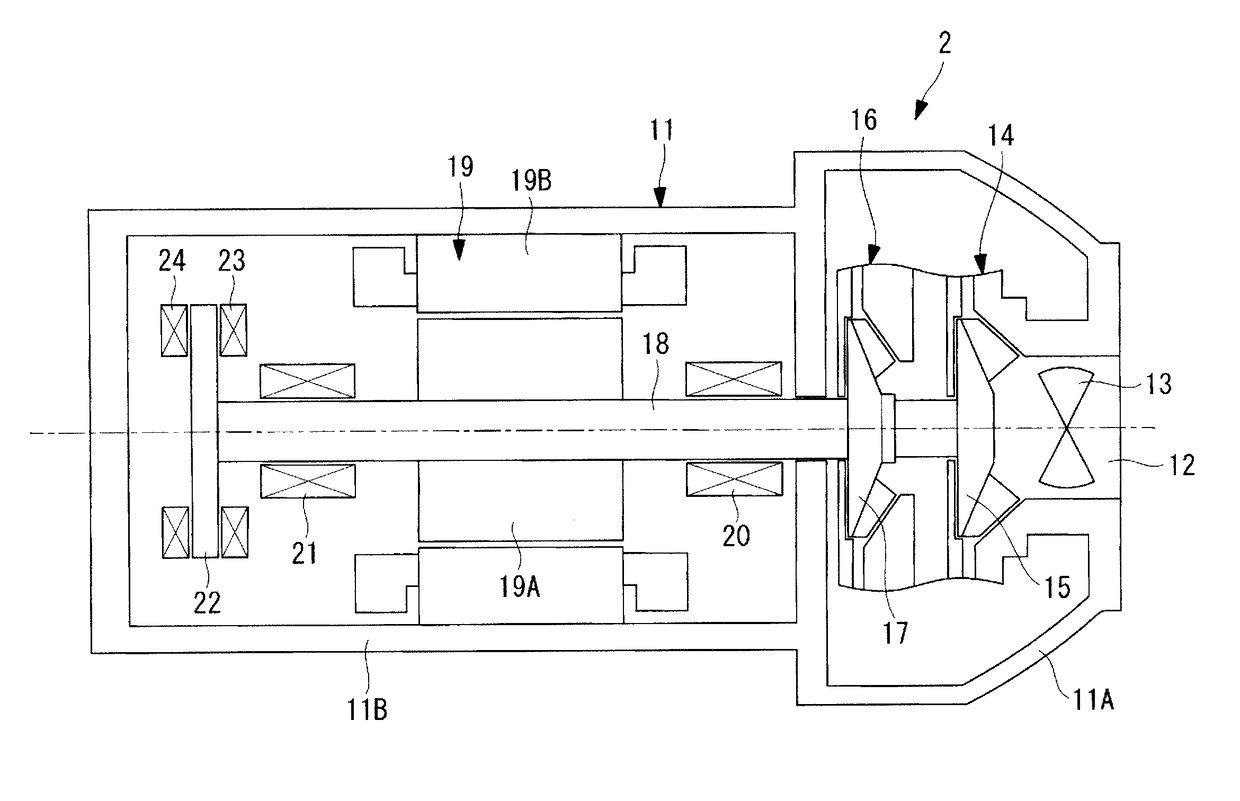
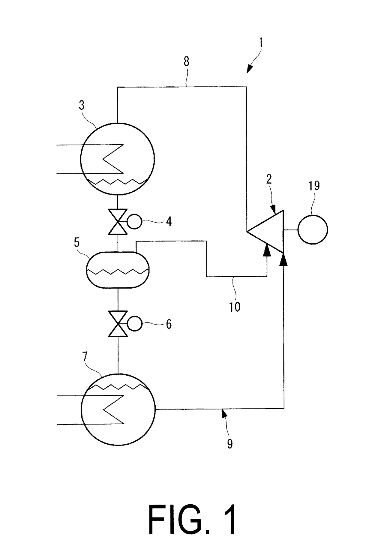
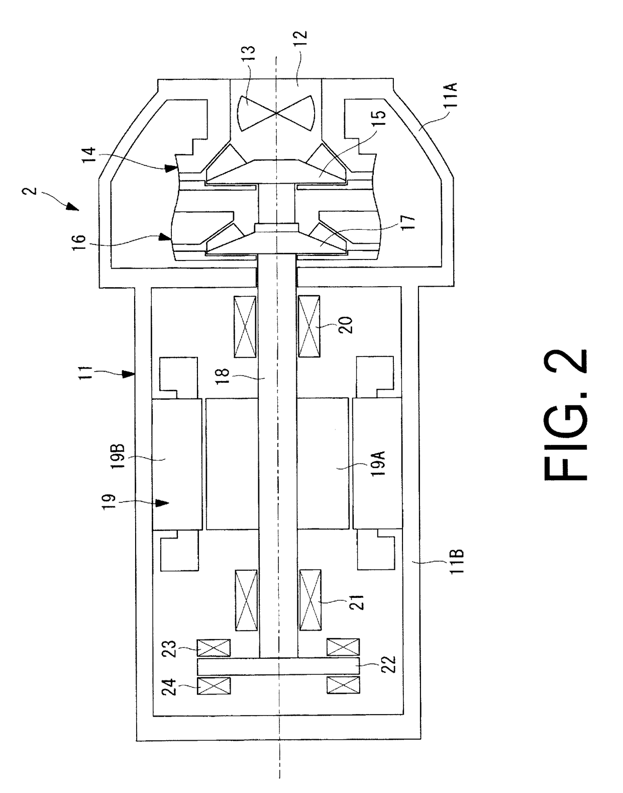
[0027]FIG. 1 illustrates a configuration diagram of a turbo chiller according to the first embodiment. FIG. 2 illustrates a schematic configuration diagram of a turbo compressor applied to the turbo chiller.

[0028]The turbo chiller 1, as illustrated in FIG. 1, is provided with a closed refrigeration cycle 9 in which a turbo compressor 2, a condenser 3, a first decompression device 4, a gas-liquid separator 5 that functions as an economizer, a second decompression device 6, and an evaporator 7 are connected in sequence via a refrigerant pipe (piping) 8.

[0029]The refrigeration cycle 9 of the present embodiment is further provided with a known economizer circuit 10 configured to inject the gas refrigerant separated at the gas-liquid separator 5 into the intermediate pressure refrigerant compressed at a lower stage compression portion 14 of the turbo compressor 2 via an intermediate port. The e...

second embodiment

[0045]Next, a second embodiment of the present invention will be described using FIGS. 3 and 4.

[0046]The present embodiment is different from the first embodiment in that the rotating shaft 18 is supported in a manner allowing free rotation by oil-free ceramic bearings 25, 26. Other points are similar to the first embodiment, so their descriptions are omitted here.

[0047]In the present embodiment, the rotating shaft 18 is supported in a manner allowing for free rotation by the oil-free ceramic slide bearings or rolling bearings 25, 26 (hereinafter, in the present invention, referred to as ceramic bearings) as illustrated in FIG. 3, instead of the radial magnetic bearings 20, 21 and the thrust magnetic bearings 23, 24.

[0048]The ceramic bearings 25, 26 are made from silicon nitride, have high durability, and a long lifetime despite being oil-free. In the present embodiment, the ceramic bearings 25, 26 can be cooled and lubricated by liquid refrigerant extracted from the refrigeration c...


PUM


Abstract

A turbo chiller that has an oil-free configuration, which reduces the frequency of maintenance and maintenance-induced release of refrigerant, and can achieve a reduced environmental impact by utilizing the characteristics of the low-pressure refrigerant R1233zd(E) that reaches negative pressure at a saturation temperature of 18° C. or lower. The turbo chiller comprises a refrigeration cycle that includes a turbo compressor, a condenser, a decompression device, and an evaporator connected in sequence via piping and is filled with a refrigerant; wherein the refrigerant is a low-pressure refrigerant R1233zd(E) refrigerant with low global warming potential and low ozone depletion potential; the turbo compressor has a direct drive configuration in which a rotating shaft of impellers is directly joined to a motor; and the rotating shaft is supported by magnetic bearings.

Description

TECHNICAL FIELD[0001]The present invention relates to a turbo chiller with a reduced environment impact that uses an R1233zd(E) refrigerant with a low global warming potential (GWP) and a low ozone depletion potential (ODP).BACKGROUND ART[0002]Currently, hydrofluorocarbon (HFC) refrigerants such as R134a are used in turbo chillers. HFC refrigerants, while having an ozone depletion potential (ODP) of 0, have a high global warming potential (GWP). Turbo chillers require routine maintenance in which bearings, lubricating oil, an oil filter, and the like are replaced. While maintenance is performed after recovering the refrigerant from the refrigeration cycle, unrecoverable refrigerant may remain inside the chiller, and refrigerant may be contained in the lubricating oil. As a result, some refrigerant may be released into the atmosphere. While this is not in violation of regulations, it is undesirable from the perspective of global warming.[0003]Some conventional turbo chillers have an ...

Claims


Application Information

Patent Timeline
IPC IPC(8): F25B31/00F04D29/28F04D29/053F04D29/058F25B43/00F04D29/063F04D29/58F25B1/053F25B31/02F04D17/10F04D25/02
CPCF25B31/002F04D17/10F04D29/284F04D29/053F04D29/058F04D25/02F25B2341/0662F04D29/582F25B1/053F25B31/008F25B31/006F25B31/026F25B43/006F04D29/063F04D17/122F04D25/0606F04D29/0566F04D29/5806F16C37/002F16C37/005F16C32/0489F16C33/043F16C33/109F25B2400/13F16C2360/44F25B41/39
Inventor HASEGAWA, YASUSHIUEDA, KENJIMATSUKURA, NORIYUKISUEMITSU, RYOSUKEOMURA, SHINTARO
Owner MITSUBISHI HEAVY IND THERMAL SYST
Why Eureka
Try Eureka