Carbon dioxide capture interface for power generation facilities

a technology of carbon dioxide and power generation facilities, which is applied in the direction of lighting and heating apparatus, emission prevention, combustion types, etc., can solve the problems of reducing the temperature of the flue gas, reducing the emission of carbon dioxide, and causing a greenhouse

Active Publication Date: 2017-06-08
POLVI ESKO OLAVI
View PDF1 Cites 6 Cited by
  • Summary
  • Abstract
  • Description
  • Claims
  • Application Information

AI Technical Summary

Benefits of technology

[0012]In accordance with the presently disclosed invention, a power generation facility may include a pressurized fluidized bed combustion unit with interface that makes the facility compatible with a unit for removing carbon dioxide from combustion gases. The interface may include a heat recovery steam generator that generates steam in response to feed water in combination with exhaust gasses from the pressurized fluidized bed combustion unit. A steam turbine generator can generate electrical power in response to steam that is supplied from the heat recovery steam generator. An air compressor that supplies pressurized air to the pressurized fluidized bed combustion unit can have a first drive such as a variable speed electrical motor that is electrically connected to the steam turbine generator and that is mechanically coupled to the air compressor. During transient start-up conditions, electrical power to the variable speed motor that drives the air compressor for pressurized air to the fluidized bed combustion unit can be provided from utility electric power or other source that is external to the power generation cycle disclosed herein. The air compressor also can have a second drive that may be a gas expander that receives flue gas and that is mechanically coupled to the air compressor. In an embodiment, a first heat exchanger receives flue gas fr...

Problems solved by technology

One difficulty with the use of such systems has been that they emit quantities of carbon dioxide—a greenhouse gas.
It is believed that greenhouse gases such as carbon dioxide cause a deleterious effect when released into the atmosphere in quantity.
A difficulty with such systems is that the expansion of the flue gas in the gas expander causes a drop in the tempe...

Method used


Image

  • Carbon dioxide capture interface for power generation facilities
  • Carbon dioxide capture interface for power generation facilities
  • Carbon dioxide capture interface for power generation facilities

Examples


Embodiment Construction

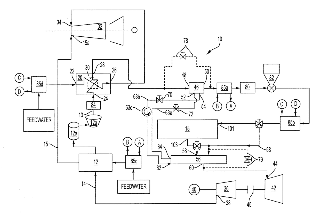
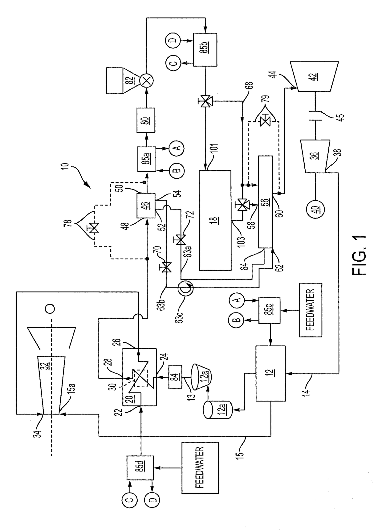
[0020]A schematic diagram of the presently preferred embodiment of the disclosed invention is shown in FIG. 1 wherein a facility 10 for the generation of electrical power includes a pressurized fluidized bed combustion unit 12 (herein “PFBCU 12”). PFBCU 12 includes a pressurized air vessel and a steam boiler that is heated by combustion of a carbon fuel bed such as a coal bed. Exhaust gas from the combustion vessel can be treated for particulate removal by one or more cyclone separators 12a and then discharged through a conduit 13. To promote more complete combustion of the coal bed in PFBCU 12, pressurized air is supplied to PFBCU 12 through an air feed 14. Steam from the boiler in PFBCU 12 is provided through line 15 to a steam turbine generator 32 to generate electrical power. In alternative embodiments, the steam from the PFBCU boiler can be used for purposes of direct heating or as an energy source.

[0021]FIG. 1 illustrates an interface for adapting the power generation facility...


PUM


Abstract

In a power generation facility (10) wherein a fluidized bed combustion unit (12) produces steam to power a steam turbine generator (32), a heat recovery steam generator (20) produces steam for the steam turbine generator. Electrical power from the steam turbine generator is conducted to a motor (40) that drives and air compressor (36). The air compressor provides pressurized air back to the fluidized bed combustion unit (12) to promote fuel combustion. Flue gas from the heat recovery steam generator is selectively conducted to a CO2 capture unit (18) and then to a gas expander (42) that assists the motor in driving the air compressor (36). A heat exchanger (46) that is upstream of the CO2 Capture Unit and a heat exchanger (56) that is downstream of the CO2 Capture Unit and upstream of the air expander have thermal fluid sides that are connected in a closed circuit. The heat exchangers (46 and 56) convey heat away from the CO2 Capture Unit and provide heat to flue gas flowing to the gas expander to avoid icing conditions in the gas expander and acid condensation in the air emission stack.

Description

BACKGROUND OF THE INVENTION[0001]Field of the Invention[0002]The presently disclosed invention relates to fossil fuel power generation facilities and, more particularly, systems for adapting such facilities for removal and capture of carbon dioxide from combustion exhaust gases.[0003]Discussion of the Prior Art[0004]Various commercial systems and process for combusting fossil fuels to generate electrical power have been in use for many years. One difficulty with the use of such systems has been that they emit quantities of carbon dioxide—a greenhouse gas. It is believed that greenhouse gases such as carbon dioxide cause a deleterious effect when released into the atmosphere in quantity. Accordingly, fossil fuel power plants have emphasized systems and methods having lower emissions of greenhouse gases.[0005]One system for more efficient combustion of fossil fuel and consequently lower carbon dioxide emissions employs technology known as pressurized fluidized bed combustion. In that ...

Claims


Application Information

Patent Timeline
IPC IPC(8): F01K7/16F22D1/02F23J15/04
CPCF01K7/16F22D1/02F23J15/04F01D15/08F01D15/10F01D25/02F01K23/062F23C10/16F23J15/02F23J15/025F23J15/08F23J2215/10F23J2215/20F23J2215/50F23J2217/10F22B31/0007F23J15/006F23J2219/10F23J2219/40
Inventor POLVI, ESKO OLAVI
Owner POLVI ESKO OLAVI
Why Eureka
Try Eureka