Method and apparatus for fast quantitative analysis of a material by laser induced breakdown spectroscopy (LIBS)

a technology of laser induced breakdown and quantitative analysis, applied in the direction of material analysis, spectrum investigation, instruments, etc., can solve the problems of preventing one from realizing real-time analysis using libs, affecting the and difficult representation sampling of bulk materials, etc., to achieve the effect of improving the sensitivity and reproducibility of libs analysis

Active Publication Date: 2017-06-15
NAT RES COUNCIL OF CANADA
View PDF5 Cites 6 Cited by
  • Summary
  • Abstract
  • Description
  • Claims
  • Application Information

AI Technical Summary

Benefits of technology

[0017]The present invention features three different regimes of ablation using the same laser for preparation of the surface of a material. The first regime for cleaning or ablating produces a reproducible and controlled ablation that removes the undesired coating layer at a longer pulse duration (few hundreds of ns), followed by a second regime using pulses of shorter duration (few nanosecond pulses) to polish that surface from any residual coating and giving the material a smooth surface which doesn't lead to repeated oxidation. The third regime for analysis scans inside the cleaned area with overlapped spots in order to avoid the edges of the cleaned area. The third regime probe, collinear with the first, has a smaller sampling area and intermediate pulse duration in between that of the first and second pulse durations to allow generation of low background analytical plasma. The plasma emission is then collected and separated in an optical spectrometer.
[0019]Many laser systems produce a near-Gaussian energy distribution within the laser beam, which limits the depth resolution achievable with the LIBS technique as it produces cone-shaped craters with a non-negligible peripheral contribution to the ablated mass. The present invention allows one to obtain a more homogenous ablation by using high quality beam distribution. The ablation depth is controlled using a given number of laser shots or laser passes. The invention also allows one to perform an analysis of the surface at the bottom of the ablated zone, without any contribution from the crater wall and at constant fluence on the target allowing for reproducible measurements.
[0027]This invention also enhances the sensitivity and the reproducibility of the LIBS technique by using high repetition long pulse duration laser-induced plasmas with low background continuum.

Problems solved by technology

The major challenge for these industries is increasing productivity, reducing costs, and maximizing benefits from existing equipment.
The site-by-site method has a number of problems that make representative sampling of the bulk material difficult and prevents one from realizing real-time analysis using LIBS.
The plasma produced by the laser also interacts with the wall of the crater and induces some mixing of material, which complicates the analysis by LIBS and impacts analytical precision and accuracy, in particular in the region close to an interface.
Another problem is the limited thickness of the ablated mass by the laser pulses in the nanosecond regime which is in the order of a few tens of nanometers on, for example, metals.
Although appropriate to use for cleaning / ablating coating layers having a thickness of a few micrometers, such methods cannot be used for coating layers having a thickness of a few hundred of micrometers or more due to the time required which prevents one from doing a fast analysis by LIBS.
Lack of or poor sensitivity as compared to other analytical schemes is also a problem with using LIBS in this context.
In fact, the large background emission (continuum radiation) of the hot laser-induced plasmas can mask and reduce the signal-to-noise ratios of the atomic emission signal from the analyte species, resulting in a lack of or poor sensitivity.
This approach, however, deals with depth profilometry at one position and cannot be applied for scanning the surface.
The above-mentioned approaches have failed, among others, to eliminate the interaction between the laser and the wall of the crater.
Furthermore, these approaches can only be used for one position and for layers in the order of a few micrometers, which is a problem for samples or materials having non-homogenous or heterogeneous compositions due to difficulties in obtaining representative samples.

Method used


Image

  • Method and apparatus for fast quantitative analysis of a material by laser induced breakdown spectroscopy (LIBS)
  • Method and apparatus for fast quantitative analysis of a material by laser induced breakdown spectroscopy (LIBS)
  • Method and apparatus for fast quantitative analysis of a material by laser induced breakdown spectroscopy (LIBS)

Examples


Embodiment Construction

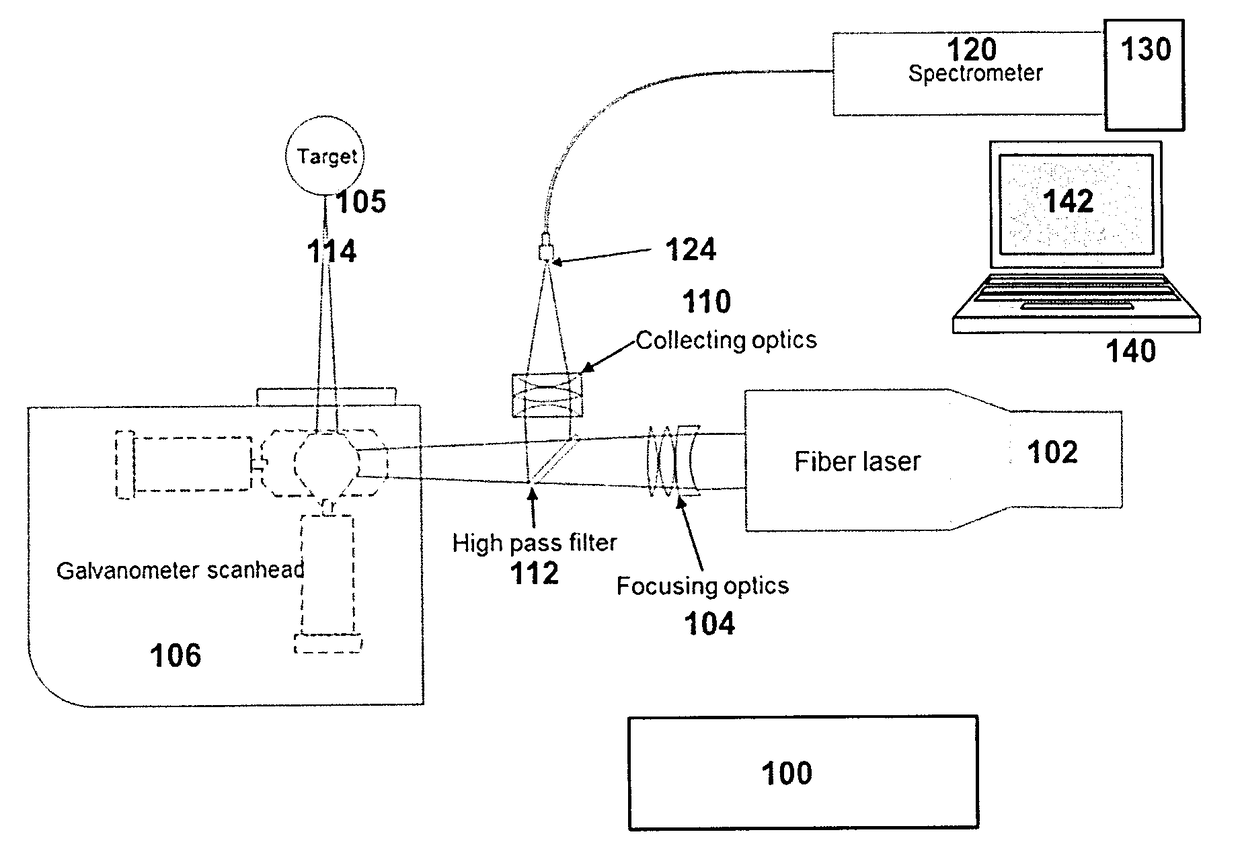
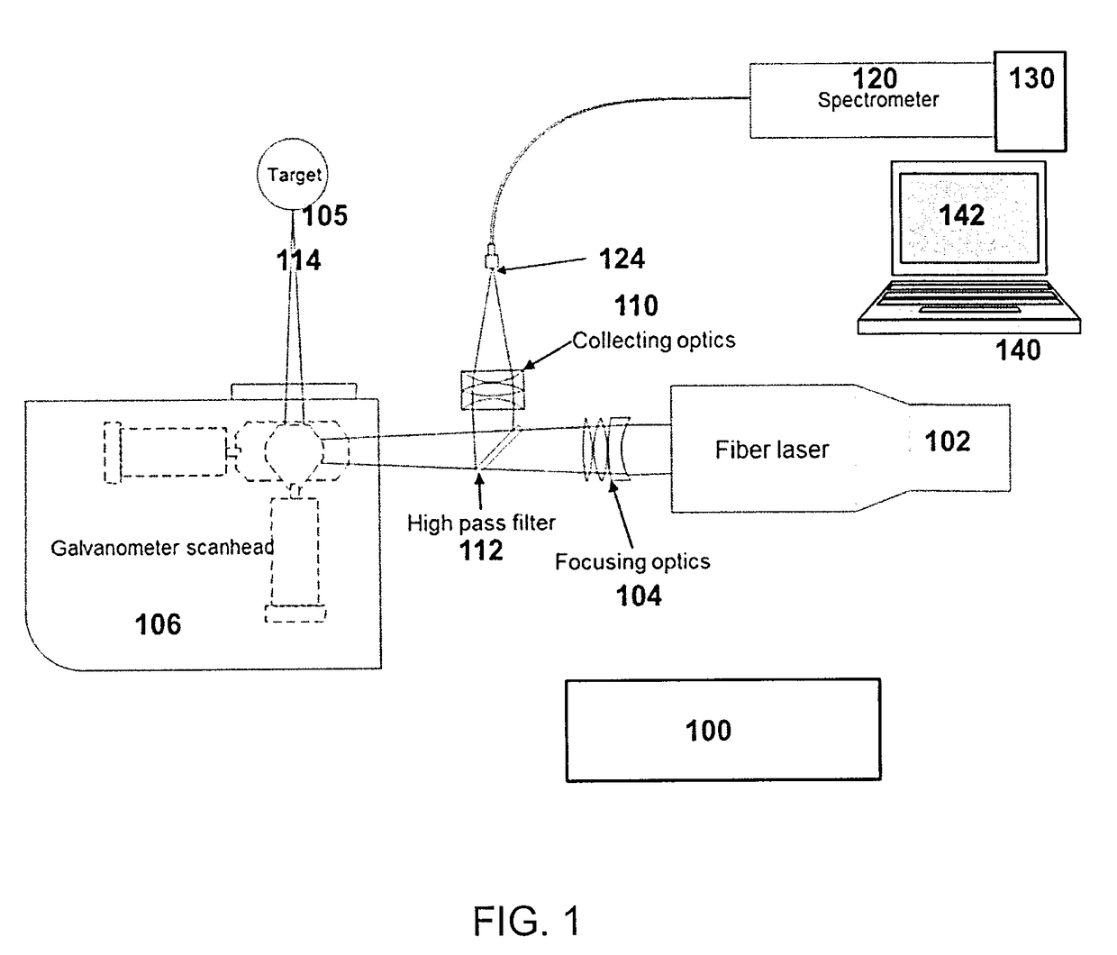
[0041]FIG. 1 shows a schematic overview of a LIBS apparatus 100 according to one embodiment of the present invention. The individual components shown in outline or designated by blocks in these figures are all well-known in the LIBS arts, and their specific construction and operation are not critical to the operation or best mode for carrying out the present invention. The apparatus 100 generally includes a pulsed fiber laser 102, a galvanometer 106, a high pass filter 112, a spectrometer 120 and a system computer 140. The apparatus 100 is configured to generate laser pulses from the fiber pulsed laser 102. The laser pulses are focused onto a sample 105 with a lens 104 to produce a plasma plume 114 of the sample 105. The galvanometer scan head 106 is electrically coupled with the system computer 140 for sending a displacement error signal to automatically correct positioning of the sample 105 during an ablating process as described further below. That galvanometer can be programmed ...


PUM

PropertyMeasurementUnit
wavelengthaaaaaaaaaa
sizeaaaaaaaaaa
spot sizeaaaaaaaaaa

Abstract

The invention discloses an apparatus and method for use with Laser Induced Breakdown Spectroscopy (LIBS) systems that can be applied to the real time analysis of various materials. The invention, in one aspect, provides a layer-by-layer method to remove the undesired coating layer of a material in which a pulsed laser is coupled with high speed scanning optics. To prepare the surface for LIBS, (i) a pulsed laser beam is scanned over an area of the surface to ablate the surface coating layer; (ii) the laser parameters are changed (i.e. pulse duration is made smaller) and the area scanned again to polish the surface; and (iii) the laser parameters are changed again (i.e. pulse duration is made smaller yet again) and the area scanned again with spectrometric analysis of the plasma plume created by the laser (i.e. LIBS is performed).

Description

FIELD OF THE INVENTION[0001]This invention relates to a method and apparatus for preparing the surface of a material for a LIBS measurement. In particular, the invention is directed to a method and apparatus used to remove the undesired coating layer of a material in order to allow for an accurate and real time analysis of the bulk material using LIBS.BACKGROUND OF THE INVENTION[0002]LIBS is a well-known analytical technique for determining the constitution of a sample material that involves focusing a laser beam onto the surface of the sample with high enough power density (i.e. irradiance) to vaporize and ionize a small part of the sample material to produce a plasma or spark having an elemental composition representative of the material. Optical emissions from the plasma plume are collected with light collection optics, and the spectral distribution (i.e. intensity as a function of wavelength) of the collected optical emissions is analyzed in a spectrometer that produces informat...

Claims


Application Information

Patent Timeline
Patent Type & Authority Applications(United States)
IPC IPC(8): G01N21/71G01J3/443
CPCG01J3/443G01N21/718
Inventor DOUCET, FRANCOISSABSABI, MOHAMADOZCAN, LUTFU-CELEBIGRAVEL, JEAN-FRANCOISBOISMENU, FRANCIS
Owner NAT RES COUNCIL OF CANADA
Why Eureka
Try Eureka