Magnetism measuring device, gas cell, manufacturing method of magnetism measuring device, and manufacturing method of gas cell

a manufacturing method and gas cell technology, applied in the direction of single device manufacturing, magnetic measurement, instruments, etc., can solve the problems of reducing the number of manufacturing processes due to re-processing, the ampoule may not come out of the reservoir through the opening, and the processing performed in the depth direction through laser light irradiation may not proceed, so as to reduce the number of manufacturing processes and improve productivity. , the effect of reducing the manufacturing yield

Inactive Publication Date: 2017-07-13
SEIKO EPSON CORP
View PDF5 Cites 27 Cited by
  • Summary
  • Abstract
  • Description
  • Claims
  • Application Information

AI Technical Summary

Benefits of technology

[0008]An advantage of some aspects of the invention is that it provides a gas cell, a magnetism measuring device, and manufacturing methods thereof, in which a member for generating an alkali metal gas, such as an ampoule accommodated in a reservoir, can be prevented from coming out through an opening and is held in a stable state in the reservoir to reliably generate the alkali metal gas through laser light irradiation, a reduction in manufacturing yield or an increase in the number of manufacturing processes can be prevented, and productivity can be improved.

Problems solved by technology

However, for example, in a case where the ampoule is inserted through an opening provided in the reservoir to be accommodated in the reservoir and the opening is blocked and sealed by a sealing portion, during handling through a process of accommodating the ampoule to the sealing process or during sealing by the sealing portion, there is concern that the ampoule may come out from the reservoir through the opening.
In addition, when the position of the ampoule varies individually and deviates from a position of irradiation with laser light during the irradiation of the ampoule with the laser light, or when the ampoule in the reservoir is unstable and the ampoule moves due to an impact caused by the laser light irradiation, there is concern that processing performed in a depth direction through the laser light irradiation may not proceed and the gas of the alkali metal may not be generated.
In a case of these problems, a reduction in manufacturing yield or an increase in the number of manufacturing processes due to re-processing may be incurred.

Method used


Image

  • Magnetism measuring device, gas cell, manufacturing method of magnetism measuring device, and manufacturing method of gas cell
  • Magnetism measuring device, gas cell, manufacturing method of magnetism measuring device, and manufacturing method of gas cell
  • Magnetism measuring device, gas cell, manufacturing method of magnetism measuring device, and manufacturing method of gas cell

Examples


first embodiment

Configuration of Magnetism Measuring Device

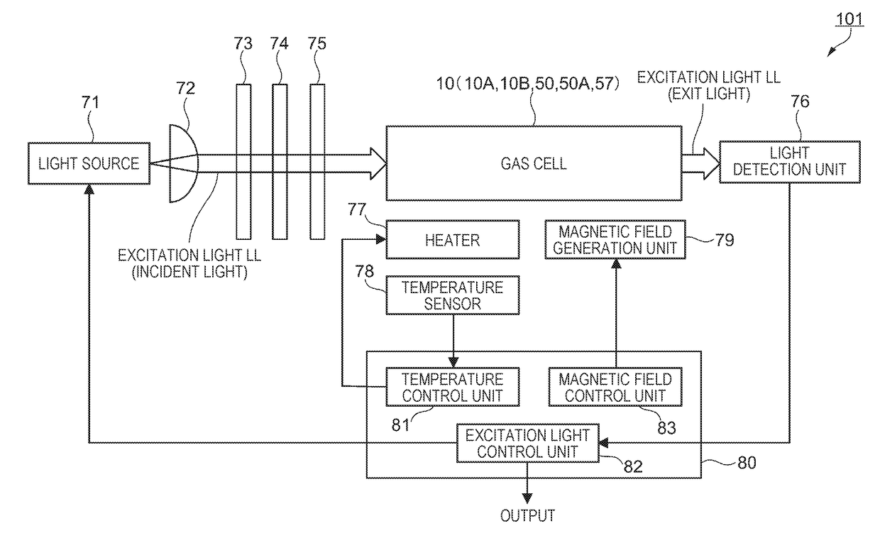
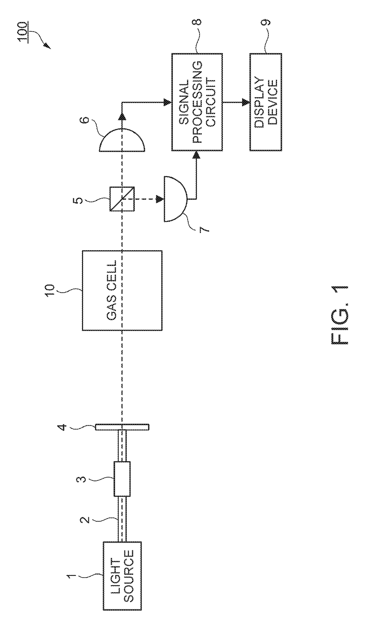
[0073]The configuration of a magnetism measuring device according to a first embodiment will be described with reference to FIG. 1. FIG. 1 is a block diagram illustrating the configuration of the magnetism measuring device according to this embodiment. A magnetism measuring device 100 according to this embodiment is a magnetism measuring device which uses nonlinear magneto-optical rotation (NMOR). The magnetism measuring device 100 is used in, for example, a living body state measuring device (magnetocardiography, magnetoencephalography, or the like) which measures a weak magnetic field generated from a living body such as a magnetic field from the heart (cardiac magnetism) or a magnetic field from the brain (cerebral magnetism). The magnetism measuring device 100 may also be used in a metal detector or the like.

[0074]As illustrated in FIG. 1, the magnetism measuring device 100 includes a light source 1, an optical fiber 2, a connector 3, a...

second embodiment

[0117]A second embodiment is different from the first embodiment in that a solid containing the alkali metal is not the ampoule but a pill. However, the configuration of the cell portion is substantially the same. The configurations of a gas cell according to the second ampoule and a pill used in the gas cell will be described with reference to FIGS. 7A to 8A. In addition, like elements which are common to those of the first embodiment are denoted by like reference numerals, and description thereof will be omitted.

Configuration of Pill

[0118]First, the configuration of the pill as the solid containing the alkali metal according to the second embodiment will be described. FIG. 8A is a perspective view of the pill according to the second embodiment. As illustrated in FIG. 8A, a pill 30 according to the second embodiment is, for example, substantially cylindrical. The diameter φ of the cylinder of the pill 30 is, for example, about 1 mm, and the height t of the cylinder of the pill 30 i...

modification example 1

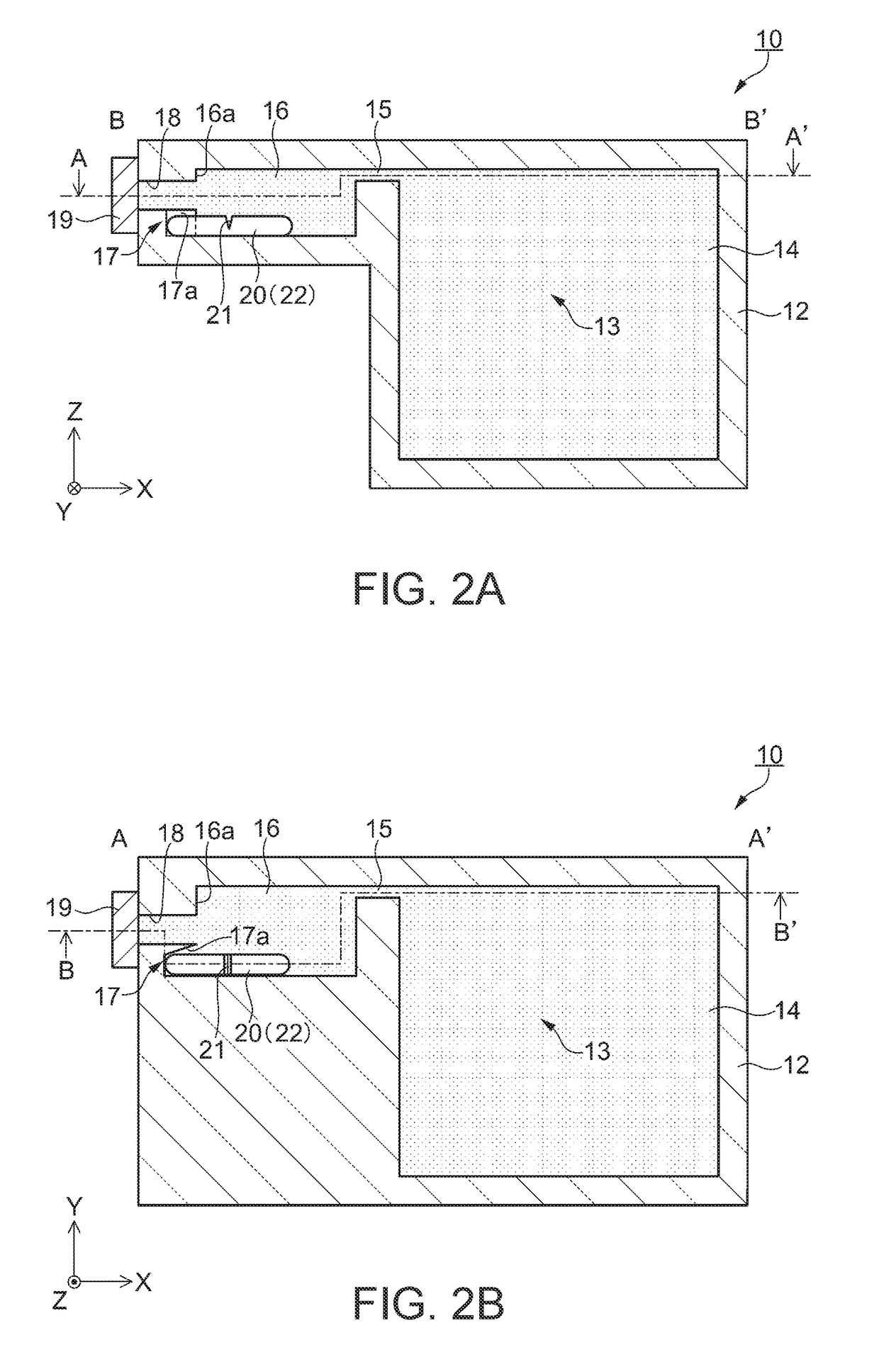
[0135]The magnetism measuring device and the gas cells of the above-described embodiments are configured so that the holding portion provided in the reservoir is formed as the recessed portion recessed in the longitudinal direction and the inclined surface is provided. However, the invention is not limited to this configuration. The holding portion may have a configuration other than that in the above-described embodiments. FIGS. 11A to 11C are partial sectional plan views illustrating configuration examples of the gas cell according to Modification Example 1. FIGS. 11A to 11C correspond to the sectional plan view illustrated in FIG. 2B.

[0136]As illustrated in FIG. 11A, a cell portion 12A of a gas cell 10B includes a holding portion 11 formed as a recessed portion which is recessed from the wall surface 16a of the reservoir 16 toward the −X direction side along the longitudinal direction. A surface 11a of the holding portion 11 along the longitudinal direction of the ampoule 20 is n...


PUM


Abstract

A magnetism measuring device which measures a magnetic field, includes: a gas cell including a cell portion which includes a main chamber, a reservoir that communicates with the main chamber and has a longitudinal direction, and an opening that is provided in the longitudinal direction of the reservoir on a side opposite to the main chamber, a sealing portion which seals the opening, and an alkali metal gas filling the main chamber and the reservoir; and a holding portion provided in the reservoir along the longitudinal direction.

Description

[0001]This application claims the benefit of Japanese Patent Application No. 2016-3290, filed on Jan. 12, 2016. The content of the aforementioned application is hereby incorporated by reference in its entirety.BACKGROUND[0002]1. Technical Field[0003]The present invention relates to a magnetism measuring device, a gas cell, a manufacturing method of a magnetism measuring device, and a manufacturing method of a gas cell.[0004]2. Related Art[0005]An optical pumping type magnetism measuring device which irradiates a gas cell, in which an alkali metal gas is sealed, with linearly polarized light and measures a magnetic field according to a rotation angle of a polarization plane is known. JP-A-2012-183290 discloses a magnetism measuring device provided with a gas cell, in which an ampoule containing an alkali metal sealed therein is accommodated in a reservoir (ampoule accommodation chamber), a through-hole is formed in a glass tube of the ampoule by irradiating the ampoule with laser lig...

Claims


Application Information

Patent Timeline
Patent Type & Authority Applications(United States)
IPC IPC(8): G01R33/032G01R33/00
CPCG01R33/0052G01R33/032G01R33/26
Inventor FUJII, EIICHINAGASAKA, KIMIO
Owner SEIKO EPSON CORP
Why Eureka
Try Eureka