Segmented linear ion trap for enhanced ion activation and storage

a linear ion and enhanced ion technology, applied in the field of enhanced linear ion traps, can solve the problems of limited narrow time window for interactions, limited voltage amplitude accessible for the intermediate state, etc., and achieve the effect of facilitating the release or receiving of ions and enhancing collision induced dissociation

Active Publication Date: 2017-08-03
FASMATECH SCI & TECH
View PDF3 Cites 21 Cited by
  • Summary
  • Abstract
  • Description
  • Claims
  • Application Information

AI Technical Summary

Benefits of technology

[0022]It is desirable to pulse gas to access elevated pressures over a short period of time while minimizing the gas load to neighboring vacuum compartments. Elevated gas pressures are necessary to enhance collision induced dissociation, cool ions via collisions during processing or transfer between trapping regions. Pulse gas also allows for operating the linear ion trap during ion isolation at low pressure. Preferably, the duration of a gas pulse for optimizing injection and transfer is less than 20 ms and at any instant in time pressure is uniform throughout the linear ion trap. The duration of a gas pulse for optimizing CID can be arranged to extend over a longer period of time. More than one pulse valve can be connected to the linear ion trap for delivering different gases. Most preferably, the linear ion trap is differentially pumped.
[0023]The DC electrical potential control and consequently the potential energy adjustment functionality of the present invention require switching at least one of the DC field components between three different DC levels. Switching DC electrical potential or DC voltages applied to segments between three or more DC levels is necessary to fully exploit the advantages associated with ion potential energy control in a linear ion trap designed with at least two trapping regions, most preferably in a linear ion trap designed with at least three trapping regions. Switching between three or more levels facilitates the releasing or receiving ions from or in a trapping respectively. Therefore, the linear ion trap of the present invention further requires the use of multiple state high voltage switching technology. In a preferred circuitry design high voltage MOSFET transistors are connected in series to enable DC switching between at least three levels of the DC electrical potential. In another preferred circuitry design a series of analogue multiplexers are employed where each multiplexer provides multiple output levels of each of the DC electrical potentials applied to generate the DC field components distributed across the linear ion trap. Individual analogue multiplexers or transistors connected in series can either be connected to individual segments to create DC field components for axial control of ion motion. Alternatively, RF-free electrodes immersed in the RF field can be biased to create the trapping regions for axial confinement and to transfer ions across the linear ion trap.

Problems solved by technology

The activation-dissociation methods available are limited to Collision Induced Dissociation (CID) and Electron Transfer Dissociation (ETD) and so far no more than two activation methods can be performed in tandem in the same linear ion trap.
In addition to the constrains in the mass range of the ions stored successfully in the ion trap imposed by three-state RF trapping, the voltage amplitude accessible for the intermediate state is also severely limited and so is the accessible energy range available during interaction.
Another disadvantage of the method disclosed for operating a linear ion trap is the narrow time window for interactions to occur, which is limited to less than ⅓ of the waveform period.

Method used


Image

  • Segmented linear ion trap for  enhanced  ion activation and storage
  • Segmented linear ion trap for  enhanced  ion activation and storage
  • Segmented linear ion trap for  enhanced  ion activation and storage

Examples


Embodiment Construction

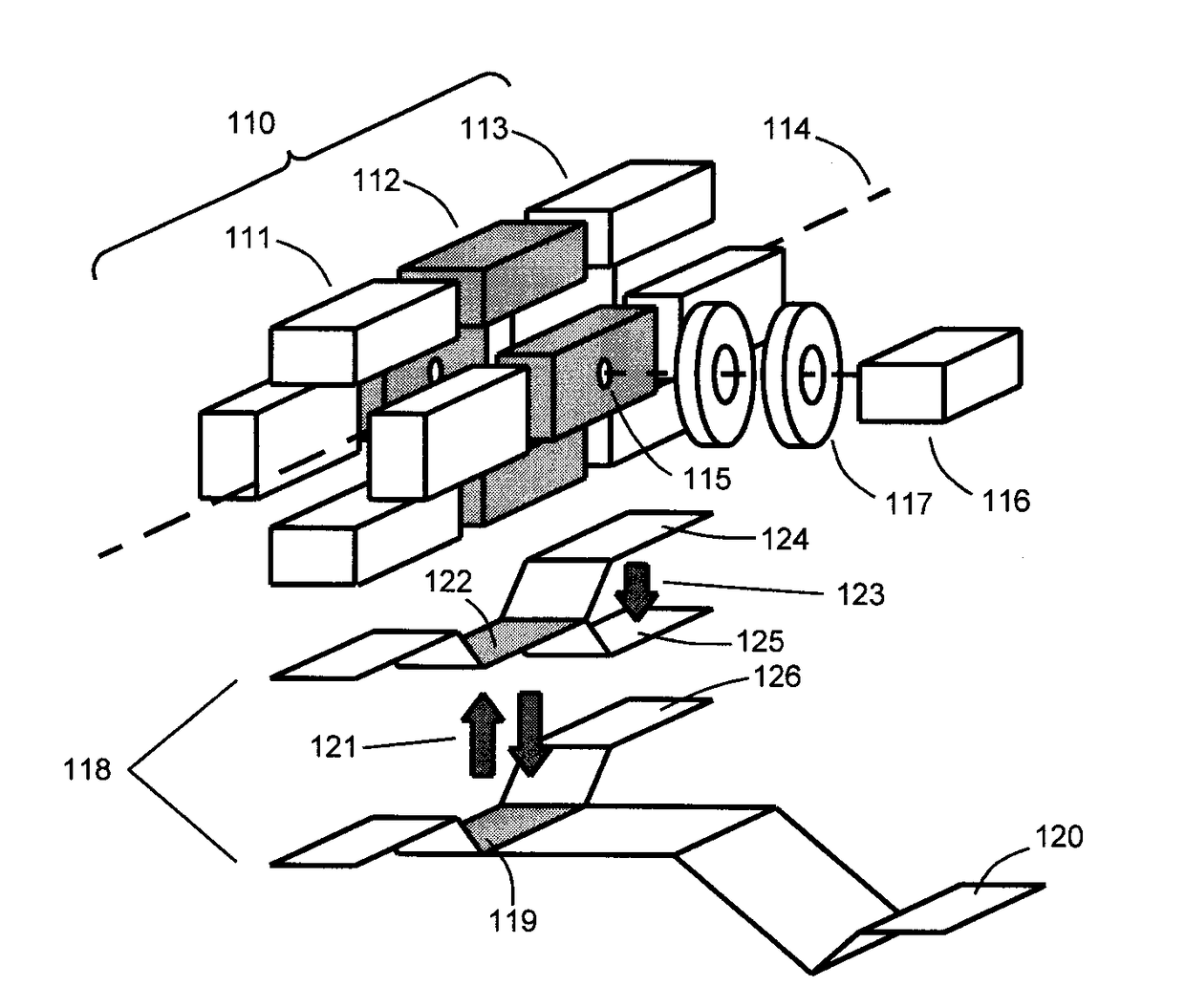
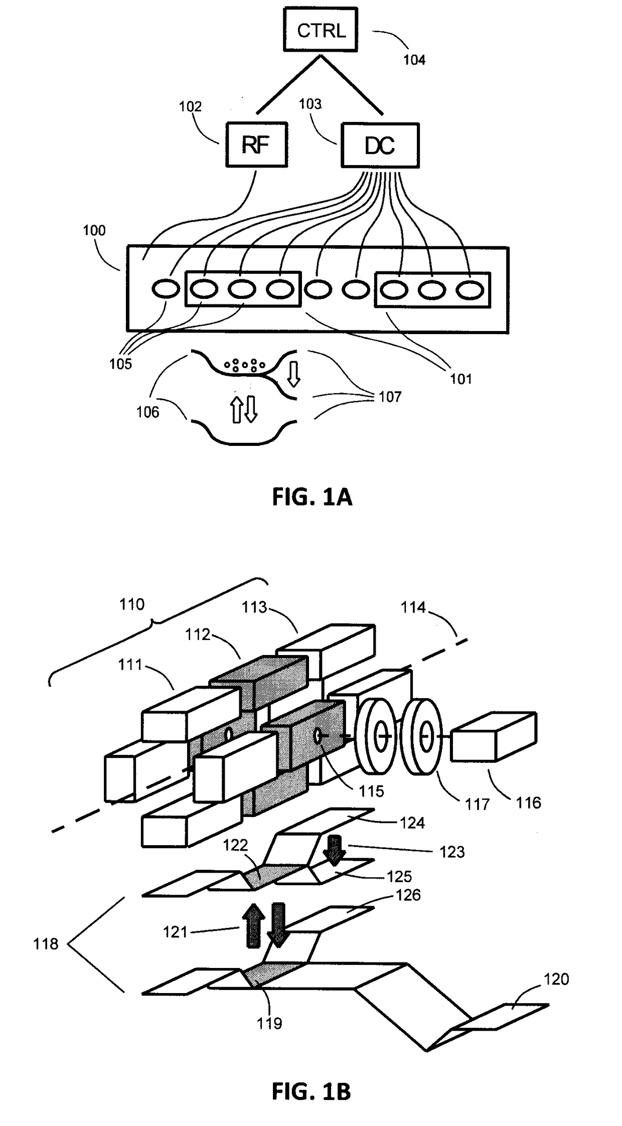
[0052]A general description of a linear quadrupole ion trap of the present invention is provided with reference to FIG. 1A. The linear ion trap 100 is connected to a RF generator 102 producing two RF waveforms, each applied to a pair of pole electrodes of the linear ion trap forming a RF trapping field component to trap ions radially. The linear ion trap 100 is also connected to a multi-output DC generator 103 producing multiple DC electrical potentials forming multiple DC field components 105 superimposed onto the RF field component and distributed across the length of the ion trap to control ions axially. A control unit 104 (e.g., FPGA control unit 346 further described below with reference to FIG. 3C) is used to define the characteristics of the RF waveforms and also the timing and the switching of the DC electrical potentials between different levels. The linear ion trap is preferably configured with two discrete trapping regions 101 for processing ions therein. The levels of th...


PUM


Abstract

A linear ion trap includes at least two discrete trapping regions for processing ions, a RF electrical potential generator, a multi-output DC electrical potential generator, and a control unit. The RF electrical potential generator produces two RF waveforms each applied to a pair of pole electrodes of the linear ion trap forming a RF trapping field component to trap ions radially. The multi-output DC electrical potential generator produces multiple DC field components superimposed to the RF field component and distributed across the length of the linear ion trap to control ions axially. The control unit switches the DC electrical potentials and corresponding DC field components collectively forming a first trapping region populated with ions to alter ion potential energy from a first level to a second level, and enables a first ion processing step in at least one of the first and second levels.

Description

BACKGROUND[0001]Field of the Invention[0002]The technical field of the invention relates to ion analysis using mass spectrometry. More particularly, to the development of a segmented linear ion trap to enable an extended range of ion processing techniques applied sequentially and facilitated by controlling the RF and DC electrical potential of trapping regions. Specifically, to the development of electronics and associated new techniques for ion trap operation.[0003]Background Information[0004]Linear ion traps have evolved into extremely powerful and versatile analytical devices and constitute a significant and indispensible instrumentation section in modern mass spectrometry. Deployed as stand-alone mass analyzers or integrated in hybrid mass spectrometers, the range of tools and methods available for manipulating gas phase ions are remarkably wide. Linear ion traps are ideal platforms for developing and testing novel designs to achieve enhanced performance capabilities and further...

Claims


Application Information

Patent Timeline
Patent Type & Authority Applications(United States)
IPC IPC(8): H01J49/42
CPCH01J49/4225H01J49/005H01J49/0054H01J49/426G01N27/622H01J49/062H01J49/4265
Inventor PAPANASTASIOU, DIMITRISRAPTAKIS, EMMANUEL
Owner FASMATECH SCI & TECH
Why Eureka
Try Eureka