Chemical-free production of graphene-reinforced inorganic matrix composites

a graphene-reinforced inorganic matrix, chemical-free technology, applied in the direction of additive manufacturing, process efficiency improvement, transportation and packaging, etc., can solve the problem of difficult to disperse more than 25% of graphene in an inorganic matrix using conventional methods, and achieve the effect of reducing cost, reducing process size, and optimizing material properties and throughpu

Active Publication Date: 2017-08-10
GLOBAL GRAPHENE GRP INC
View PDF3 Cites 101 Cited by
  • Summary
  • Abstract
  • Description
  • Claims
  • Application Information

AI Technical Summary

Benefits of technology

[0122]One significant advantage of the present invention as compared to prior art is flexibility of selecting carrier materials. Virtually any inorganic material that is solid at room temperature or at the process temperature of the energy impact device can be used as a solid carrier material to make graphene / inorganic nanocomposites. This process can be used to create graphene / inorganic composites of various form factors, including pellets, powder, continuous filaments, and various shapes according to mold / tooling shapes.
[0123]Another significant advantage of the present invention as compared to prior art is flexibility of selecting the carbon material input into the process—no size reduction in needed. Input carbon material can be graphite in a flake morphology, raw mined graphite (without any size reduction), industrial waste from graphite anodes or paper, or industrial byproducts such as needle coke. This flexibility enables significant cost reduction for industrial scale production.
[0124]In a desired embodiment, the presently invented method is carried out in an automated and / or continuous manner. For instance, as illustrated in FIG. 5, the mixture of graphite particles 1 and solid carrier particles 2 (plus optional impacting balls) is delivered by a conveyer belt 3 and fed into a continuous ball mill 4. After ball milling to form graphene-coated solid carrier particles, the product mixture (possibly also containing some residual graphite particles and optional impacting balls) is discharged from the ball mill apparatus 4 into a screening device (e.g. a rotary drum 5) to separate graphene-coated solid carrier particles from residual graphite particles (if any) and impacting balls (if any). This separation operation may be assisted by a magnetic separator 6 if the impacting balls are ferromagnetic (e.g. balls of Fe, Co, Ni, or Mn-based metal). The graphene-coated carrier particles may be delivered into a powder classifier, a cyclone, and or an electrostatic separator. The particles may be further processed by melting 7, pressing 8, or grinding / pelletizing apparatus 9. These procedures can be fully automated. The process may include characterization or classification of the output material and recycling of insufficiently processed material into the continuous energy impacting device. The process may include weight monitoring of the load in the continuous energy impacting device to optimize material properties and throughput.
[0125]Another preferred embodiment of this method is melting of the coated inorganic pellets and spraying them into a surface to create a graphene / inorganic nanocomposite coating.
[0126]Graphene sheets transferred to carrier solid surfaces have a significant proportion of surfaces that correspond to the edge planes of graphite crystals. The carbon atoms at the edge planes are reactive and must contain some heteroatom or group to satisfy carbon valency. There are many types of functional groups (e.g. hydroxyl and carboxylic) that are naturally present at the edge or surface of graphene nano platelets produced through transfer to a solid carrier particle. The impact-induced kinetic energy experienced by the carrier particles are of sufficient energy and intensity to chemically activate the edges and even surfaces of graphene sheets coated on carrier particle surfaces (e.g. creating highly active sites or free radicals). Provided that certain chemical species containing desired chemical function groups (e.g. —NH2, Br—, etc.) are included in the impacting chamber, these functional groups can be imparted to graphene edges and / or surfaces. In other words, production and chemical functionalization of graphene sheets can be accomplished concurrently by including appropriate chemical compounds in the impacting chamber. In summary, a major advantage of the present invention over other processes is the simplicity of simultaneous production and modification of surface chemistry.
[0127]Graphene platelets derived by this process may be functionalized through the inclusion of various chemical species in the impacting chamber. In each group of chemical species discussed below, we selected 2 or 3 chemical species for functionalization studies.

Problems solved by technology

It may be noted that it has been difficult to disperse more than 25% of graphene in an inorganic matrix by using the conventional approaches.

Method used


Image

  • Chemical-free production of graphene-reinforced inorganic matrix composites
  • Chemical-free production of graphene-reinforced inorganic matrix composites
  • Chemical-free production of graphene-reinforced inorganic matrix composites

Examples


example 1

Reinforced Copper Matrix Composite

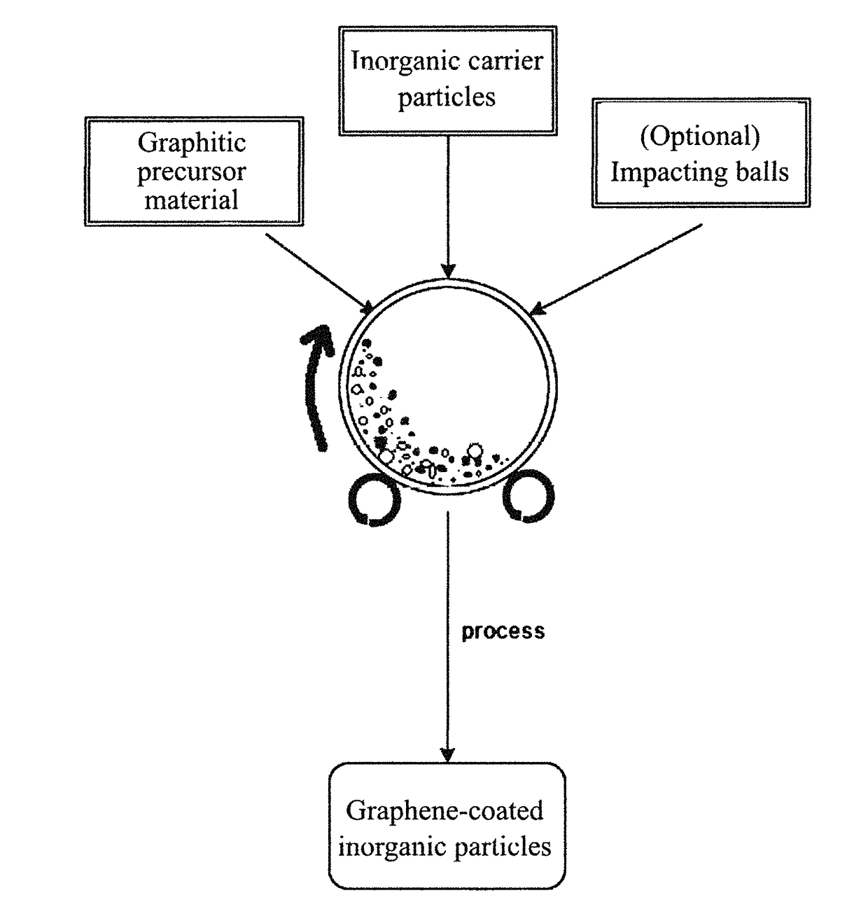
[0137]In an experiment, 1 kg of copper powder, 100 grams of flake graphite, 50 mesh (average particle size 0.18 mm; Asbury Carbons, Asbury N.J.) and 110 grams of magnetic stainless steel pins (Raytech Industries, Middletown Conn.) were placed in a high-energy ball mill container. The ball mill was operated at 300 rpm for 4 hours. The container lid was removed and stainless steel pins were removed via magnetic separation. Particles of the inorganic carrier material were found to be coated with a dark layer, which was verified to be graphene by Raman spectroscopy. Carrier material was placed over a 50 mesh sieve and a small amount of unprocessed flake graphite was removed.

[0138]A 10 gram sample of the material was compacted into a disk by pressing and then sintered in a furnace with flowing argon at an appropriate temperature. An additional 10 gram sample was pressed and densified by hot isostatic pressing (HIP).

[0139]A 10 gram sample of the above mat...

example 2

lized Graphene Reinforced Copper-Matrix Inorganic Composite

[0140]The process of example 1 was replicated with the inclusion of 50 grams of urea as a nitrogen source. The coated powder created was formed into disks using the same processes as example 1.

example 3

Reinforced Tin Composite

[0141]In an experiment, 2 grams of 99.9% purity tin powder and 0.25 grams HOPG were placed in a resonant acoustic mill (Lab Ram, Resodyn Inc, Butte Mont.) along with stainless steel balls and processed for 5 minutes. Subsequently, the coated tin particles were compacted at room temperature, melted at 240° C., and solidified to form a graphene-reinforced tin matrix composite disk.


PUM

PropertyMeasurementUnit
thicknessaaaaaaaaaa
thicknessaaaaaaaaaa
temperatureaaaaaaaaaa

Abstract

Provided is a simple, fast, scalable, and environmentally benign method of producing a graphene-reinforced inorganic matrix composite directly from a graphitic material, the method comprising: (a) mixing multiple particles of a graphitic material and multiple particles of an inorganic solid carrier material to form a mixture in an impacting chamber of an energy impacting apparatus; (b) operating the energy impacting apparatus with a frequency and an intensity for a length of time sufficient for peeling off graphene sheets from the graphitic material and transferring the graphene sheets to surfaces of solid inorganic carrier material particles to produce graphene coated or graphene-embedded inorganic particles inside the impacting chamber; and (c) forming graphene-coated or graphene-embedded inorganic particles into the graphene-reinforced inorganic matrix composite. Also provided is a mass of the graphene-coated or graphene-embedded inorganic particles produced by this method.

Description

FIELD OF THE INVENTION[0001]The present invention relates to the art of graphene materials and, in particular, to an environmentally benign and cost-effective method of producing graphene-reinforced inorganic matrix composites.BACKGROUND[0002]A single-layer graphene sheet is composed of carbon atoms occupying a two-dimensional hexagonal lattice. Multi-layer graphene is a platelet composed of more than one graphene plane. Individual single-layer graphene sheets and multi-layer graphene platelets are herein collectively called nano graphene platelets (NGPs) or graphene materials. NGPs include pristine graphene (essentially 99% of carbon atoms), slightly oxidized graphene (<5% by weight of oxygen), graphene oxide (≧5% by weight of oxygen), slightly fluorinated graphene (<5% by weight of fluorine), graphene fluoride ((≧5% by weight of fluorine), other halogenated graphene, and chemically functionalized graphene.[0003]NGPs have been found to have a range of unusual physical, chemic...

Claims


Application Information

Patent Timeline
Patent Type & Authority Applications(United States)
IPC IPC(8): B22F9/04B22F3/105C03C14/00B22F1/102B22F1/16
CPCB22F9/04C03C14/008B22F3/1055C03C2214/17B33Y70/00B22F2301/10B22F2301/052B22F2301/30B33Y10/00B22F2009/043C22C1/1084C22C26/00C22C47/14C22C49/14B22F2998/10Y02P10/25B22F1/16B22F10/28B22F10/34B22F1/102B22F3/14B22F3/15B22F2003/1051B22F2003/1054B22F3/20B22F9/082B22F9/026B22F10/25B33Y70/10
Inventor ZHAMU, ARUNAJANG, BOR Z.
Owner GLOBAL GRAPHENE GRP INC
Why Eureka
Try Eureka