On-board power supply apparatus
a power supply and power supply technology, applied in power supply testing, electrical control, instruments, etc., can solve problems such as loss, and achieve the effect of improving operational reliability
- Summary
- Abstract
- Description
- Claims
- Application Information
AI Technical Summary
Benefits of technology
Problems solved by technology
Method used
Image
Examples
first embodiment
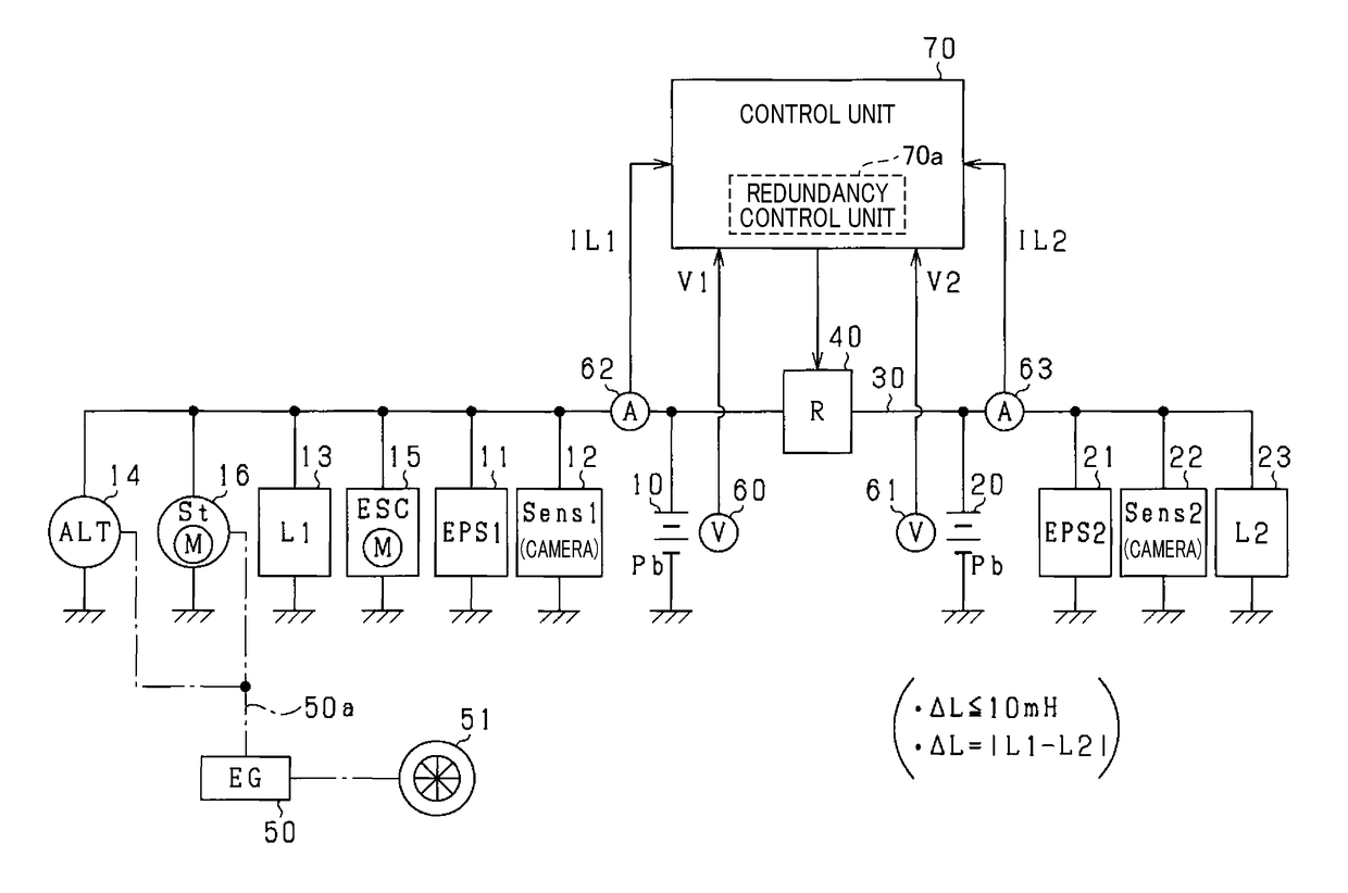
[0062]A first embodiment of an on-board power supply apparatus will hereinafter be described with reference to the drawings. According to the present embodiment, the power supply apparatus is presumed to be mounted in a vehicle that includes an engine as an on-board main machine.
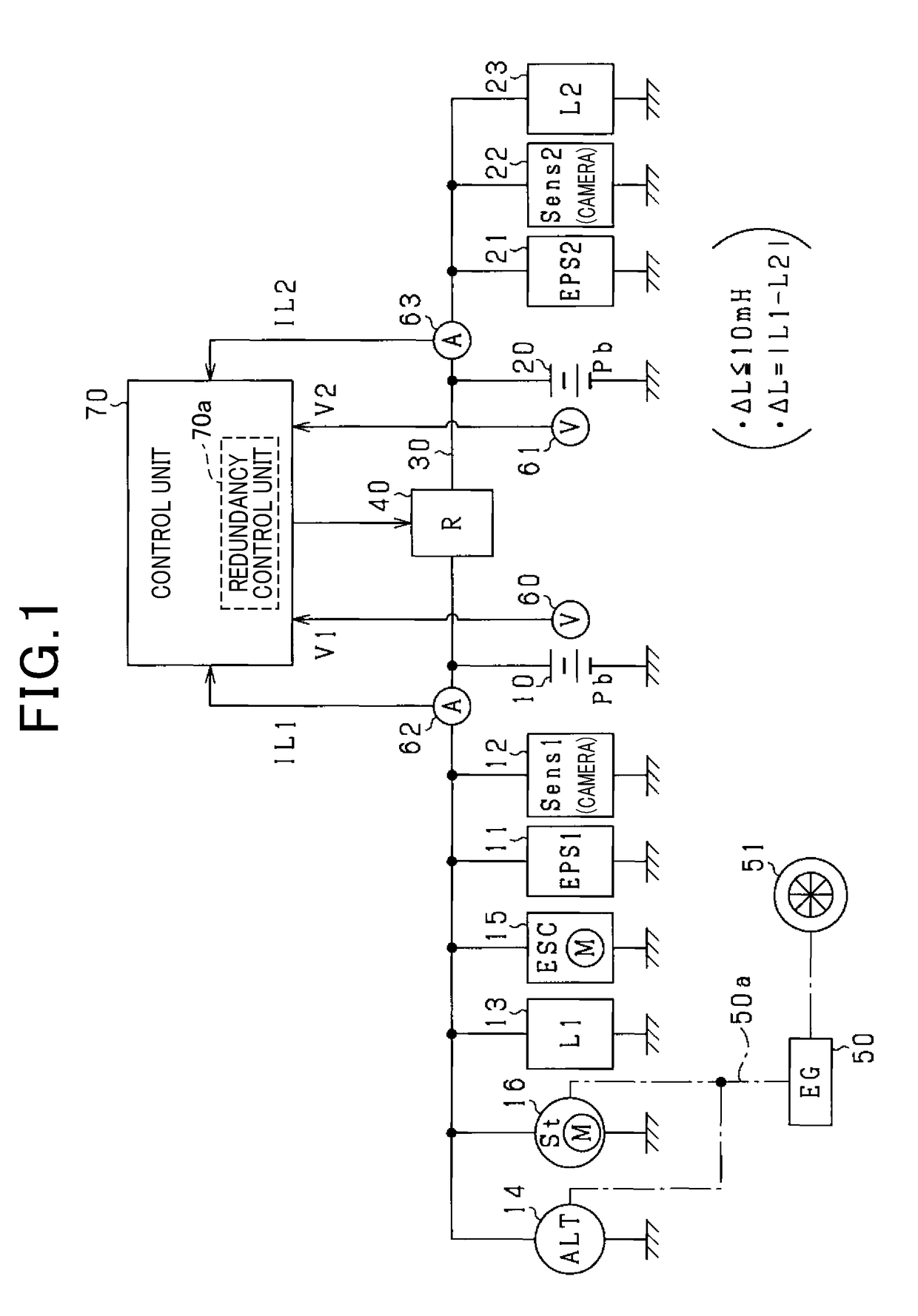
[0063]As shown in FIG. 1, the vehicle includes an on-board power supply system. The power supply system includes a first battery 10 and a second battery 20. According to the present embodiment, the first battery 10 and the second battery 20 are lead batteries that have the same full-charge capacity. The respective negative terminals of the first battery 10 and the second battery 20 are grounded to the vehicle body. According to the present embodiment, the respective full-charge capacities of the first battery 10 and the second battery 20 refer to capacities obtained by the full-charge capacity required to operate each on-board electrical load being equally halved. Therefore, the physical structures of the fi...
second embodiment
[0105]A second embodiment will be described below with reference to the drawings, mainly focusing on the differences from the above-described first embodiment. According to the present embodiment, as shown at step S34 in FIG. 5, the method for determining whether or not to issue notification of the rotation-recommendation information is modified. In FIG. 5, processes that are identical to the processes shown in foregoing FIG. 4 are given the same reference numbers for convenience.
[0106]As shown in FIG. 5, at step S34, the control unit 70 determines whether or not a resistance difference ΔR is greater than a predetermined value Rα. The resistance difference ΔR is a value obtained by the second internal resistance value Rc2 being subtracted from the first internal resistance value Rc1. According to the present embodiment, the process at step S34 corresponds to a main determining unit.
[0107]According to the above-described present embodiment as well, effects similar to those according ...
third embodiment
[0108]A third embodiment will be described below with reference to the drawings, mainly focusing on the differences from the above-described first embodiment. According to the present embodiment, as shown in FIG. 6 and FIG. 7, a safety plug 31 that serves as a blocking member is provided on the connection path 30. In FIG. 6 and FIG. 7, configurations that are identical to the configurations shown in foregoing FIG. 1 are given the same reference numbers for convenience.
[0109]As shown in FIG. 6 and FIG. 7, the safety plug 31 electrically connects the first battery 10 and the second battery 20 in a state in which the safety plug 31 is inserted into the connection path 30. Meanwhile, as a result of the user removing the safety plug 31 from the connection path 30, the first battery 10 and the second battery 20 are electrically blocked from each other.
[0110]In FIG. 6 and FIG. 7, the positive and negative terminals of the first battery 10 are indicated by 10p and 10n. The positive and nega...
PUM
 Abstract
Description
Claims
Application Information
 - R&D
- Intellectual Property
- Life Sciences
- Materials
- Tech Scout
- Unparalleled Data Quality
- Higher Quality Content
- 60% Fewer Hallucinations
Browse by: Latest US Patents, China's latest patents, Technical Efficacy Thesaurus, Application Domain, Technology Topic, Popular Technical Reports.
© 2025 PatSnap. All rights reserved.Legal|Privacy policy|Modern Slavery Act Transparency Statement|Sitemap|About US| Contact US: help@patsnap.com


