Integrated microwave-to-optical single-photon transducer with strain-induced electro-optic material

a single-photon transducer and optical technology, applied in the field of conversion, can solve the problems of complex existing methods for converting between microwave signals and optical signals, difficult implementation in solid-state systems, and more difficult use of microwave photons for long-range communication purposes

Active Publication Date: 2017-08-10
IBM CORP
View PDF1 Cites 8 Cited by
  • Summary
  • Abstract
  • Description
  • Claims
  • Application Information

AI Technical Summary

Benefits of technology

[0006]A transducer includes a substrate having a cavity with a diameter that supports whispering gallery modes at a frequency of an input signal. A focusing structure in the cavity focuses the electric field of the input signal. A resonator directly under the focusing structure has a crystalline structure that generates an electro-optic effect when exposed to electrical fields. An electric field of the input signal modulates an output signal in the resonator via the electro-optic effect.
[0007]A quantum computing device includes a qubit configured to provide a first signal at a first frequency. A transducer coupled to the qubit and includes a substrate having a cylindrical cavity with a diameter that supports whispering gallery modes at the first frequency. There is a central pin in the cavity. A resonator is positioned directly under the central pin. The resonator has a crystalline structure that generat...

Problems solved by technology

However, microwave photons are more difficult to use for long-range communication purposes, due to high thermal background noise and high loss when such signals propagate in waveguides.
Existing approaches to converting between microwave signals and optical signals are complicated, difficult to implement in solid state systems, or difficult to optimize.
One of the problems of using such resonators i...

Method used


Image

  • Integrated microwave-to-optical single-photon transducer with strain-induced electro-optic material
  • Integrated microwave-to-optical single-photon transducer with strain-induced electro-optic material
  • Integrated microwave-to-optical single-photon transducer with strain-induced electro-optic material

Examples


Embodiment Construction

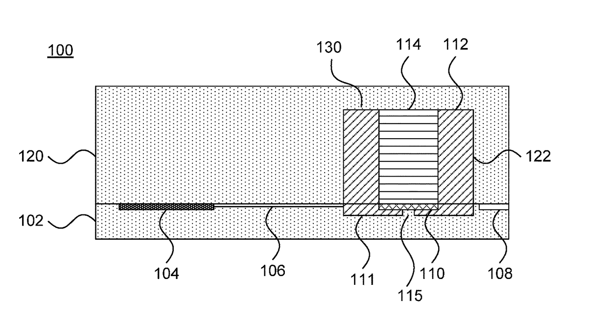
[0020]Embodiments of the present invention provide coupling between single-photon microwave signals and single-photon infrared / optical signals via the electro-optic effect using superconducting microwave and optical cavities. Each cavity incorporates an electro-optic material, with the electro-optic effect being induced by a straining material. Coupling takes place at the quantum level, with signal levels being about a single photon. The present embodiments may be implemented on one chip that may be fabricated using standard semiconductor fabrication processes.

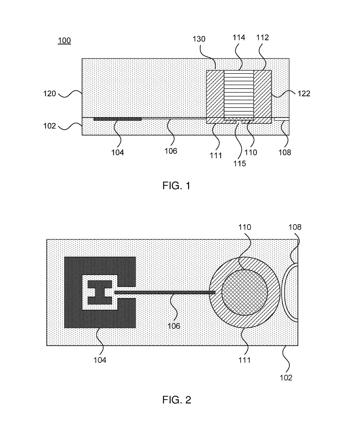
[0021]Referring now to the drawings in which like numerals represent the same or similar elements and initially to FIG. 1, a cross-sectional view of a microwave-to-optical transducer 100 is shown. A bottom substrate 102 is shown as having, e.g., a quantum computing device 104 (a “qubit”) that provides, e.g., single-photon level microwave signals along a superconducting channel 106 to a transducing cavity 130. It is specificall...


PUM


Abstract

Transducers and methods of making the same include a substrate having a cavity with a diameter that supports whispering gallery modes at a frequency of an input signal. A focusing structure in the cavity focuses the electric field of the input signal. A resonator directly under the focusing structure has a crystalline structure that generates an electro-optic effect when exposed to electrical fields. An electric field of the input signal modulates an output signal in the resonator via the electro-optic effect.

Description

BACKGROUND[0001]Technical Field[0002]The present invention relates to conversion between a microwave and an optical domain and, more particularly, to a transducer to convert single-photon microwave signals to optical signals.[0003]Description of the Related Art[0004]Various communication protocols rely on optical fibers because of their low loss, high bandwidth, low background noise, and the ease of routing. Optical fibers can also be used for sending quantum information in the form of single photons or coherent states. On the other hand, many viable quantum processing architectures operate at microwave frequencies. The high amplitude stability of microwave structures allows precise controls on quantum bits (qubits) that enable high-fidelity gate operations. However, microwave photons are more difficult to use for long-range communication purposes, due to high thermal background noise and high loss when such signals propagate in waveguides.[0005]Existing approaches to converting bet...

Claims


Application Information

Patent Timeline
IPC IPC(8): G02F1/01G06N99/00G02B6/293
CPCG02F1/011G02F2203/15G06N99/002G02B6/29341G02F1/0102H01P7/086G02F2201/17G02F2203/50G06N10/00B82Y10/00B82Y20/00G02F1/03H01P7/065H01S3/082H10N69/00H10N60/80
Inventor BISHOP, LEV S.FILIPP, STEFANGAMBETTA, JAY M.ORCUTT, JASON S.PAIK, HANHEE
Owner IBM CORP
Why Eureka
Try Eureka