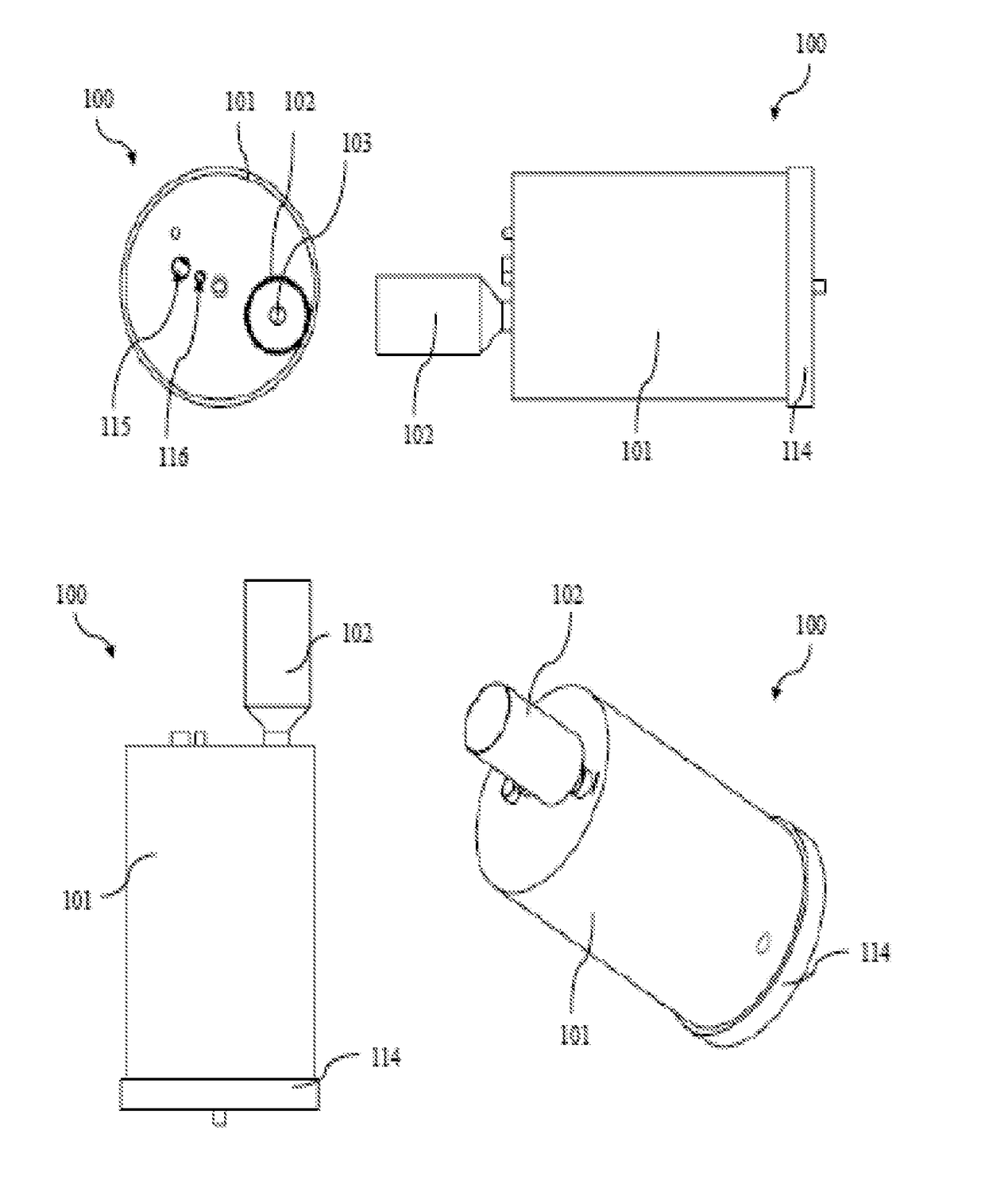
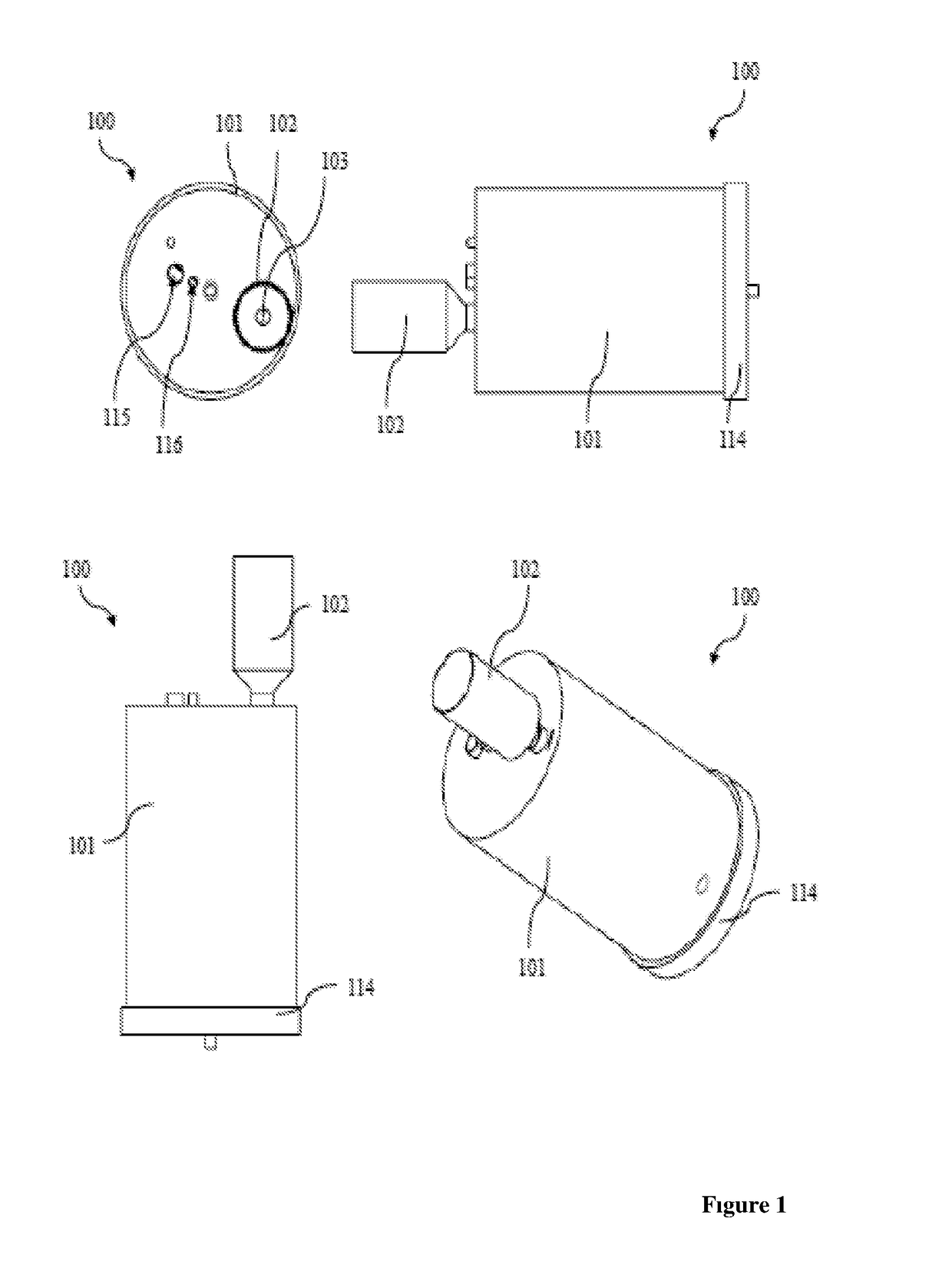
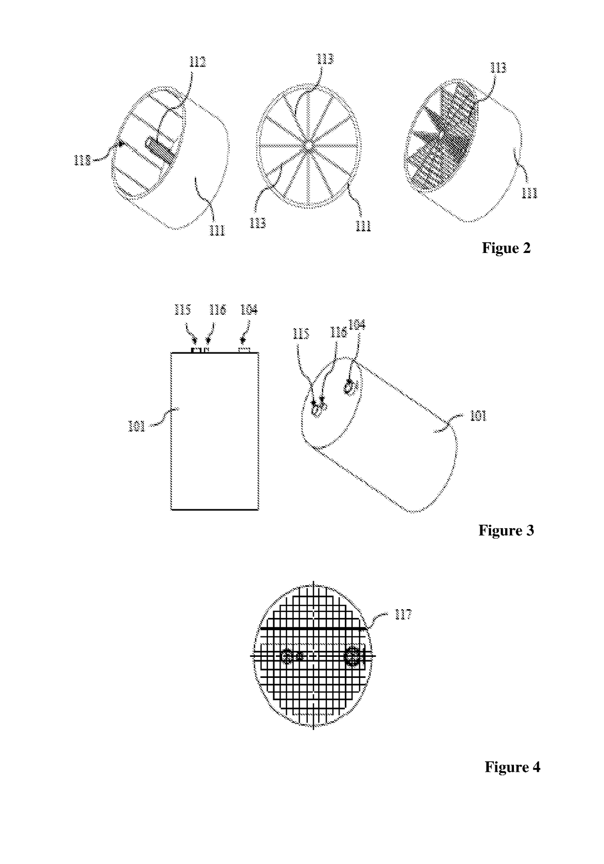
Cartridge structure designed for generation of hydrogen gas

a technology of hydrogen gas and cartridge structure, which is applied in the direction of gas generation devices, fuel cells, inorganic chemistry, etc., can solve the problems of large power requirements, inability to utilise materials as efficiently as desired, and significant risks for human health and environment, and achieves the effect of convenient disassembly and cleaning the system and convenient storag

Active Publication Date: 2017-08-17
TURKIYE ENERJI NUKLEER & MADEN ARASTIRMA KURUMU
View PDF0 Cites 3 Cited by
  • Summary
  • Abstract
  • Description
  • Claims
  • Application Information

AI Technical Summary

Benefits of technology

[0018]Another objective of the invention is to provide a cartridge structure designed for generation of hydrogen gas which has a modular structure to enable the user to easily disassemble and clean t

Problems solved by technology

Systems developed for this purpose have many adverse effects, including use of chemicals that can cause significant risks for human health and environment, large power requirements, the inability to utilise the materials as efficiently as desired, the inability to utilise the catalysers in an efficient way, the large volumes of space required for these systems, and the fact that solid wastes in the system block the product output ports.
However, the systems in the current state of art frequently face problems like accumulations in the system due to failure to properly secure the hollow fibres, the hollow fibres not being able to maintain their integrity, the inability to clean hollow fibre surfaces, and the unsecured hollow fibres blocking flow paths and preventing flow and thus decreasing efficiency.
These systems require extra energy for driving the cylinders and production of these cylinders is a costly process.
It is generally unlikely to be able to reuse the system components, and both input materials and final products come with storage problems.
However, use of strong acids in such applications constitute a serious hazard for human health and environment in case of a potential leak or rupture.
However, since it is not possible to implement a continuous operation in this system, it causes loss of time and fails to provide an efficient solution.
The fact that the system can only meet simple and small energy needs while requiring a very large volume of space demonstrates that it will have a very low efficiency.
Here, the solid waste created when the reaction of solution passing through the densely packed hollow

Method used


Image

  • Cartridge structure designed for generation of hydrogen gas
  • Cartridge structure designed for generation of hydrogen gas
  • Cartridge structure designed for generation of hydrogen gas

Examples


example 1

[0237]Surface area of 1 hollow fibre (HF)=450*12+1885*7=18600 mm2 (internal and external)[0238]Total catalyser surface area in the system (7 HF)=18600*7=130000 mm2 [0239]H2 gas flow rate obtained on a surface area of 4510 mm2=260 ml / min[0240]Total H2 gas flow rate obtained from the catalyser surface in the system=7.37 L / min[0241]System volme=75 mm*75 mm*π*113 mm=0.5 L

[0242](75 mm=radius of cylindrical system, 113 mm-=height of system)

[0243]Assuming;[0244]Hollow fibres (311) are smooth; and[0245]Only the system volume is accounted, and tank volumes are not accounted in the calculation;[0246]H2 gas flow rate obtained in a system with a volume of 1 L=(7.37 L / min)*1 L / 0.5 L=14.74 L / min. (where system volume is 1 L)

[0247]Surface area of one of the utilised hollow fibres (311) is 186 cm2. The system contains 7 pieces of hollow fibres (311). Total surface area is 1302 cm2. When the hollow fibres (311) in the system are coated with:

1. FeCl2 catalyser, the total hydrogen gas amount generated...


PUM


Abstract

This invention relates to a cartridge structure (100, 200, 300) designed for generation of hydrogen gas by means of generating hydrogen using hydride solutions (sodium hydride, lithium borohydride, potassium borohydride, ammonium borane, etc.) in presence of a catalyser. The objective of this invention is to provide a cartridge structure (100, 200, 300) designed for generation of hydrogen gas by means of generating hydrogen using continuously fed hydride solutions in presence of a catalyser.

Description

CROSS REFERENCE TO RELATED APPLICATIONS[0001]This application is the national phase of International Application No. PCT / IB2015 / 059137, filed on Nov. 26, 2015, which is based upon and claims priority to Turkish Patent Application No. 2014 / 14378, filed on Nov. 28, 2014, the entire contents of which are incorporated herein by reference.TECHNICAL FIELD[0002]This invention relates to a cartridge structure designed for generation of hydrogen gas by means of generating hydrogen using hydride solutions (sodium hydride, lithium borohydride, potassium borohydride, ammonium borane, etc.) in presence of a catalyser.BACKGROUND OF THE INVENTION[0003]Current state of the art includes many systems designed for generation of hydrogen. Systems developed for this purpose have many adverse effects, including use of chemicals that can cause significant risks for human health and environment, large power requirements, the inability to utilise the materials as efficiently as desired, the inability to uti...

Claims


Application Information

Patent Timeline
IPC IPC(8): B01J7/02B01J19/20H01M8/04082B01F7/00B01F15/02B01J19/00C01B3/04
CPCB01J7/02B01J19/0006B01J19/20C01B3/04B01F7/00291B01F7/006B01F2215/0036B01F15/024B01F15/026H01M8/04208H01M8/04216B01J2219/00164B01J2219/00186B01F7/00633C01B3/065F16K3/06F16K3/10Y02E60/36Y02E60/50B01F27/191B01F35/71755B01F35/71805B01F27/17B01F27/1125B01F2101/2204
Inventor SANKIR, MEHMETDEMIRCI SANKIR, NURDANSEMIZ, LEVENTCAN, EMRE KAANSERIN, RAMIS BERKAY
Owner TURKIYE ENERJI NUKLEER & MADEN ARASTIRMA KURUMU
Why Eureka
Try Eureka