A method and apparatus for producing biofuel in an oscillating flow production line under supercritical fluid conditions

a production line and supercritical fluid technology, applied in the direction of supercritical condition processes, bulk chemical production, carboxylic compound preparation, etc., can solve the problems of high temperature and high pressure, low heat transfer efficiency, corresponding complexity and cost of such operation conditions of reactors, etc., to improve heating and cooling effectiveness, ease maintenance and cleaning, and reduce clogging

Active Publication Date: 2017-08-17
CIRCLIA NORDIC APS
View PDF10 Cites 10 Cited by
  • Summary
  • Abstract
  • Description
  • Claims
  • Application Information

AI Technical Summary

Benefits of technology

[0036]Preferably, the conversion zone of the production line under supercritical fluid conditions (SCF) may be positioned in the production line between the said first part and the said second part of the production line to improve heating and cooling effectiveness.
[0037]Optionally, the production line, at least in the conversion zone (CZ), may have a tubular (internal) structure, preferably with a substantially unchanged inner diameter in the conversion zone (CZ), in order to lower clogging, ease maintenance and cleaning, and / or for simplifying the manufacturing process.
[0038]In some embodiment, the heating means may be supplied with heat from said cooling means via heat exchanging means for increased efficiency. Particularly, the production line in said first part and / or second part have a tubular structure, the heating exchanging means may comprise a entity made of a heat conduction material, preferably manufactured in a metal or a metal alloy, surrounding the tubular structures in both the first and / or the second part for conducting the heat from the second part to the first part in the production line. Furthermore, the heating exchanging means may comprise a fluid cooling medium for conducting the heat from the second part to the first part in the production line via fluid flow in the heat exchanging means, the fluid flow in the heat exchanging means preferably being arranged in a counter-flow relative to the biomass under conversion in the production line for further increased efficiency.
[0039]Typically, the production line may comprise a depressurizing unit at an outlet for the resulting biofuel (BF), or bio-based chemical, from the production line, by which the product is released in a semi-continuous, or continuous, manner from the production line and depressurized from the supercritical pressure in the production line. Advantageously, the oscillatory flow inducing means (OFIM) may then be operably connected to the depressurizing unit, the pressure energy released during depressurizing being, at least partly, conveyed to the pumping means (PM) and / or the oscillatory flow inducing means (OFIM) for increased pump efficiency.
[0040]In one embodiment, one, or more, hydraulic accumulators may be arranged as a pressure storage reservoir for absorbing pressure energy from the depressurizing unit for temporally storing pressure energy, and the one, or more, hydraulic accumulators being arranged for conveying, at least partly, the stored pressure energy to the oscillatory flow induction means (OFIM) thereby reusing the stored pressure energy resulting in improved cost efficiency of the production line.

Problems solved by technology

The disadvantage is the need for high temperature and high pressure, and the corresponding complexity and cost associated with such operation conditions of the reactor.
However, both of these solutions are in most cases not feasible due to on one hand large costs and pressure drops, and on the other hand low heat transfer efficiency, risk of sedimentation / clogging and low productivity.
This will be a large challenge especially in the parts of the process where the temperature is relatively low, i.e. in transport and heat exchanger zones.

Method used


Image

  • A method and apparatus for producing biofuel in an oscillating flow production line under supercritical fluid conditions
  • A method and apparatus for producing biofuel in an oscillating flow production line under supercritical fluid conditions
  • A method and apparatus for producing biofuel in an oscillating flow production line under supercritical fluid conditions

Examples


Embodiment Construction

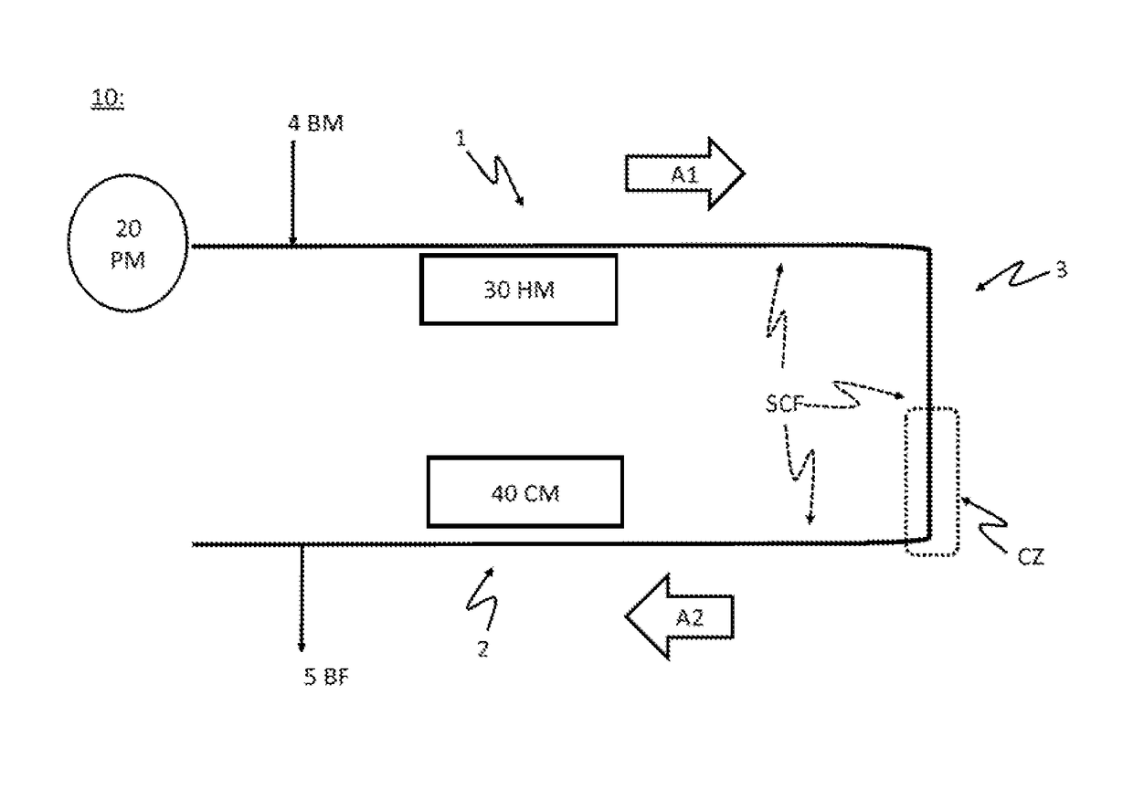
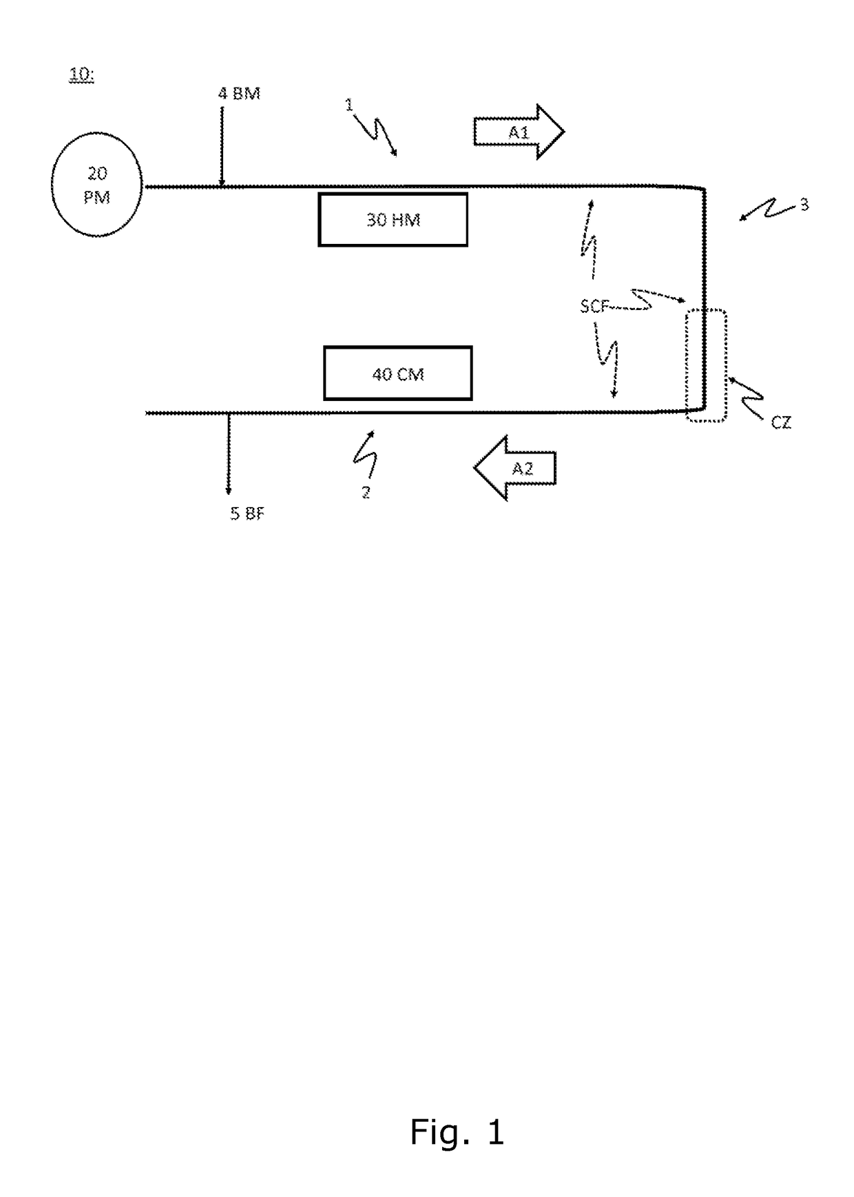
[0063]FIG. 1 is a schematic drawing of the production line 10 according to the present invention. The invention also relates to a method for producing bio-fuel BF 5 (as indicated by arrow in the lower part of the production line) or other bio-based chemicals, from biomass BM 4 entering the production line (as also indicated with arrow in the upper part of the Figure). The biomass is preferably a high-viscosity biomass, e.g. with a viscosity of 0.1 PaS or higher. The production line 10 is advantageously operated in a continuous flow. The production line 10 preferably uses thermo-chemical conversion of the biomass. The conversion may optionally be assisted by added chemicals, e.g. catalysts, acids or bases, etc. Appropriate solvents may also be added, e.g. water or other polar solvents. The production line comprises pumping means 20 PM, e.g. one or more pumps, capable of pumping the biomass 4 through the production line under a controlled pressure, P, and flow. The production line 10 ...


PUM

PropertyMeasurementUnit
pressureaaaaaaaaaa
critical temperatureaaaaaaaaaa

Abstract

The invention discloses a method for producing bio-fuel (BF) from a high-viscosity biomass using thermo-chemical conversion of the biomass in a production line (10) with pumping means (PM), heating means (HM) and cooling means (CM). The method has the steps of 1) operating the pumping means, the heating means and the cooling means so that the production line is under supercritical fluid conditions (SCF) to induce biomass conversion in a conversion zone (CZ) within the production line, and 2) operating the pumping means so that at least part of the production line is in an oscillatory flow (OF) mode. The invention is advantageous for providing an improved method for producing biofuel from a high-viscosity biomass. This is performed by an advantageous combination of two operating modes: supercritical fluid (SCF) conditions and oscillatory flow (OF).

Description

FIELD OF THE INVENTION[0001]The present invention relates to a method for operating an oscillating flow production line in a production system, e.g. a hydrothermal reactor, to produce bio-fuel, or bio-based chemicals, from biomass, such as lignin material from straw. The invention also relates to a corresponding production line or production system.BACKGROUND OF THE INVENTION[0002]Bio-fuel and bio-based chemicals production is an area of intense research and development because of the world-wide transition from fossil fuel to climate neutral fuels, such as biofuels produced from biomass, e.g. as waste product from agricultural production. Methods using super-critical fluid conditions (SCF) for biofuel production by thermo-chemical conversion have been known for some time. Notice that thermo-chemical conversion is sometimes referred to as hydrothermal conversion or hydrothermal liquefaction, the conversion mainly being controlled by the availability of additional chemicals and cataly...

Claims


Application Information

Patent Timeline
Patent Type & Authority Applications(United States)
IPC IPC(8): C07C67/08C07C51/00C07C37/00C10L1/02C07D307/34
CPCC07C67/08C10L1/026C07D307/34C10L2290/06C07C51/00C10L2200/0476C10L2270/026C07C37/004C10L1/02B01J2219/00164C10L8/00Y02E50/10Y02P20/54Y02P30/20B01J2219/00159B01J4/008B01J3/008B01J19/2415B01J19/241B01J4/007B01J3/02B01J3/042C10G1/00B01J2219/00162C10G3/40C10G2300/1011B01J19/0013B01J2219/00087
Inventor JOHANNSEN, IBADAMSEN, ANDERS PETER STUBKJ.AE BUTTED.KILSGAARD, BJORN SJORENMILKEVYCH, VIKTOR
Owner CIRCLIA NORDIC APS
Why Eureka
Try Eureka