Reactor, process, and system for the oxidation of gaseous streams

a gaseous stream and reactor technology, applied in the direction of electrochemical generators, metal/metal-oxide/metal-hydroxide catalysts, physical/chemical process catalysts, etc., can solve the problems of high cost of constructing conventional gas-to-liquid (gtl) plants, high capital investment, and high cost of constructing mega petrochemical chemical complexes. , to achieve the effect of higher molecular weigh

Inactive Publication Date: 2017-08-31
ECOCATALYTIC INC
View PDF1 Cites 27 Cited by
  • Summary
  • Abstract
  • Description
  • Claims
  • Application Information

AI Technical Summary

Problems solved by technology

Much of the newly discovered natural gas is in remote areas of the world where the cost of constructing conventional gas-to-liquid (GTL) plants is uneconomical.
These reserves are often far from large refining centers and require significant capital investment to bring these reserves to market.
One of the major challenges of conventional Fischer-Tropsch (FT) technologies is the production of a mixture of hydrocarbon products from the synthesis step.
Therefore, capital intensive mega petrochemical chemical complexes are required.
Conventional FT technology is not suitable for smaller gas sources that may be remote, isolated, or distributed around the world.

Method used


Image

  • Reactor, process, and system for the oxidation of gaseous streams
  • Reactor, process, and system for the oxidation of gaseous streams
  • Reactor, process, and system for the oxidation of gaseous streams

Examples


example 1 (working example)

[0072]An anode catalyst was prepared by mixing 42.3 g of MgO, 32.3 g of MnO2, 11.3 g of H3BO3, and 4.5 g of LiOH in sufficient deionized water to make a thick slurry. After thoroughly mixing the slurry mixture in a rotating ball mill for 2 hours, the resulting mixture was dried in air for 12 hours at 110° C. Once dried, the dry composition was heated in a furnace, in air, from room temperature to 1,000° C. at a rate of 10° C. per minute and held at 1,000° C. for 16 hours. The resulting catalyst was compressed into a cylindrical pellet of approximately 2 mm diameter and 2.5 mm length using a hydraulic press at 30,000 psi, and the pellet was analyzed by AC Impedance Spectroscopy using an Autolab potentiostat from 1 to 1,000 Hz, in air, at temperatures between 750° and 850° C. The AC conductivity was determined from the high frequency range of the spectrum and the DC impedance was interpolated from the low frequency range. The results (shown in Table 2) were compared to known average v...

example 2 (working example)

[0073]A sample of catalyst from Example 1 was placed into a micro-fixed bed reactor and produced the following activity and selectivity for the conversion of methane to higher hydrocarbons in Table 3. The sample designated as MIECA is the anode material. The methane conversion observed was in a “redox” mode, which means that methane was converted over the catalyst in the absence of air. In a separate step, the catalyst was re-activated and re-oxidized with air. The activity for methane conversion in the absence of air demonstrates that this catalyst functions to store oxygen in its structure and performs as an MIEC material.

TABLE 3Catalytic OCM conversions with anode catalystCycle Length,% Methane% C2+% C2+Sec.ConversionSelectivityYield6058.758.726.7Conditions: MIECA catalyst from Example 1; 850° C., WHSV = 1 / hr, average over 5 redox cycles.

example 3 (working example)

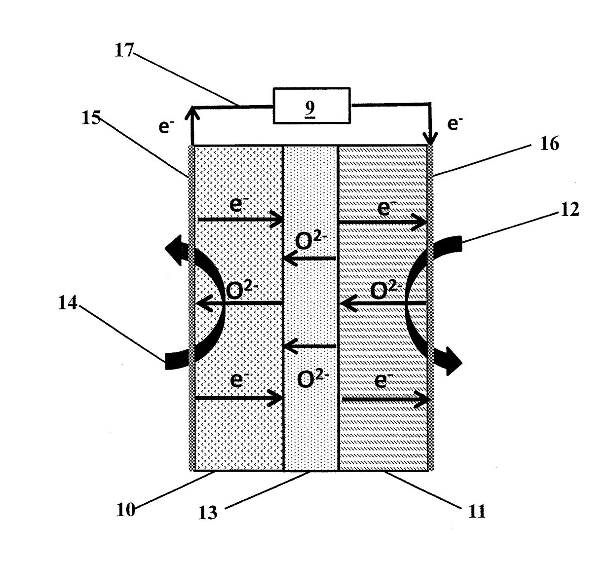
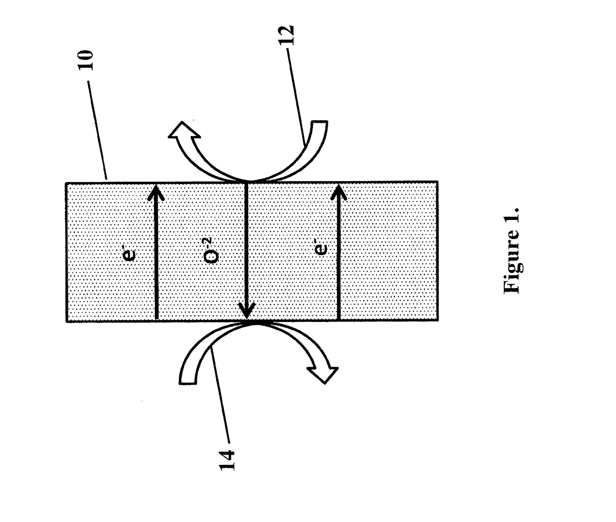
[0074]A sample of catalyst from Example 1 was tested in a button SOFC test stand with a configuration similar to FIG. 1. The membrane electrode assembly was composed of a 32 mm diameter, 300 μm thick, 8-YZS electrolyte onto which a 50 μm lanthanum-strontium-manganite cathode layer was applied. The anode surface was composed of a 50 / 50 by weight mixture of anode catalyst from Example 1 and 8-YSZ nano-particles which had been screen printed to approximately a 50 μm thickness. The total electrode working area was 1.25 cm2. Electrical contacts on both the anode and cathode were made via a silver paste and mesh. When methane was introduced to the anode chamber and air to the cathode chamber, both at 900° C., the open circuit potential showed an induction period of about one hour, eventually stabilizing to about 0.8 V, as shown in FIG. 4 and as predicted by Table 1.


PUM

PropertyMeasurementUnit
electricalaaaaaaaaaa
crystal lattice structureaaaaaaaaaa
electronic conductiveaaaaaaaaaa

Abstract

A reactor and process capable of concurrently producing electric power and selectively oxidizing gaseous components in a feed stream, such as hydrocarbons to unsaturated products, which are useful intermediates in the production of liquid fuels. The reactor includes an oxidation membrane, a reduction membrane, an electron barrier, and a conductor. The oxidation membrane and reduction membrane include an MIEC oxide. The electron barrier, located between the oxidation membrane and the reduction membrane, is configured to allow transmission of oxygen anions from the reduction membrane to the oxidation membrane and resist transmission of electrons from the oxidation membrane to the reduction membrane. The conductor conducts electrons from the oxidation membrane to the reduction membrane.

Description

CROSS REFERENCE TO RELATED APPLICATIONS[0001]The present application is a Divisional of U.S. patent application Ser. No. 14 / 289,995, filed May 29, 2014, which is a Continuation-in-Part of PCT / US2012 / 066789, filed Nov. 28, 2012, which claims priority to and benefit of U.S. Provisional Patent Application No. 61 / 566,176, filed Dec. 2, 2011, U.S. Provisional Patent Application No. 61 / 577,353, filed Dec. 19, 2011, and U.S. Provisional Patent Application No. 61 / 609,394, filed Mar. 12, 2012, the entire disclosures of all of which are incorporated herein by reference in their entireties for all purposes.FIELD OF THE INVENTION[0002]The invention relates to reactors and processes used to convert gaseous streams containing hydrocarbon gases, for example, into intermediates useful in the production of higher molecular weight products, such as liquid fuels.BACKGROUND OF THE INVENTION[0003]Driven by a growth in worldwide natural gas supply, and increasing value to liquid fuels, there is considera...

Claims


Application Information

Patent Timeline
Patent Type & Authority Applications(United States)
IPC IPC(8): C25B5/00C25B3/02H01M8/1004C07C2/84C25B3/23
CPCC25B5/00H01M8/1004C25B3/02C07C2/84B01J19/087B01J19/2475B01J8/02B01D71/024C10G50/00C10G2/34B01J37/04B01J37/08B01J23/002B01J23/34B01J35/002B01J35/0033B01J2523/00Y02E60/50C25B3/23B01J2523/11B01J2523/22B01J2523/305B01J2523/72B01D71/0271B01J2219/0803
Inventor SOFRANKO, JOHN A.
Owner ECOCATALYTIC INC
Why Eureka
Try Eureka