Reactor unit and fuel cell vehicle including reactor unit

a fuel cell vehicle and reactor technology, applied in the direction of electric variable regulation, process and machine control, instruments, etc., can solve the problems of deteriorating output performance of the converter, insufficient height direction of the device structure including the reactor unit, and insufficient cooling performance of the reactor unit. , to achieve the effect of reducing the height of the reactor unit, saving space, and sufficient cooling performan

Active Publication Date: 2017-08-31
TOYOTA JIDOSHA KK
View PDF3 Cites 4 Cited by
  • Summary
  • Abstract
  • Description
  • Claims
  • Application Information

AI Technical Summary

Benefits of technology

[0007]As stated above, it is desired to ensure sufficient cooling performance of a reactor unit including a plurality of reactors, and to save space in a height direction of the reactor unit and a device structure including the reactor unit.
[0008]A first aspect of the disclosure relates to a reactor unit including a plurality of reactors; and a cooler configured such that a cooling medium flows in an inside of the cooler and the plurality of reactors are disposed on an outside of the cooler to cool the plurality of reactors. The plurality of reactors are disposed in at least one line on a reactor cooling surface that is one of outer surfaces of the cooler. The cooler has a cooling medium flow passage that is in contact with an inner surface on a reverse side of the reactor cooling surface. The cooling medium flows linearly from an inlet portion to an outlet portion of the cooling medium flow passage. A direction in which the cooling medium flows inside the cooling medium flow passage is same as a direction in which the plurality of reactors are disposed in the at least one line. Cooling fins are provided on the inner surface on the reverse side of the reactor cooling surface. A longitudinal direction of each of the cooling fins is same as the direction in which the cooling medium flows inside the cooling medium flow passage. In the reactor unit according to the first aspect, since the plurality of reactors are disposed on the reactor cooling surface, which is one of outer surfaces of the cooler, it is possible to reduce height of the reactor unit. Also, the cooling medium flows linearly from the inlet portion to the outlet portion of the cooling medium flow passage, and the direction in which the cooling medium flows inside the cooling medium flow passage is the same as the direction in which the plurality of reactors are disposed in the at least one line. Therefore, it is possible to achieve both reduction of pressure loss in the cooling medium flow passage and improvement of the heat transfer coefficient, thereby ensuring sufficient cooling performance.
[0009]In the reactor unit according to the above-described aspect, in the cooling medium flow passage of the cooler, any one of i) a flat flow passage portion in which no cooling fin is provided and the inner surface is a flat surface, ii) a curved surface flow passage portion in which no cooling fin is provided and the inner surface is a curved surface, iii) a low fin flow passage portion including low cooling fins having a height lower than a height of the cooling fins, and iv) a small number fin flow passage portion in which the number of the cooling fins is smaller than the number of the cooling fins at a position corresponding to each of the plurality of reactors, may be provided at a position corresponding to a gap between the reactors adjacent to each other in the direction in which the plurality of reactors are disposed in the at least one line. With this configuration, turbulence is increased in the cooling medium flow in the cooling medium flow passage at the position corresponding to the gap between the reactors adjacent to each other. Thus, it is possible to prevent deterioration of cooling performance caused by a reduction in the heat transfer coefficient of the cooler due to a temperature boundary layer formed near a wall surface of the cooling medium flow passage.
[0010]A second aspect of the disclosure relates to a fuel cell vehicle including a fuel cell; the reactor unit according to the first aspect; and a DC-DC converter that converts output voltage of the fuel cell. The fuel cell is disposed in a front compartment of the fuel cell vehicle, and the reactor unit included in the DC-DC converter is disposed above the fuel cell such that the plurality of reactors are disposed in a lower side and the cooler is disposed in an upper side. In the fuel cell vehicle according to the second aspect, the reactor unit, which has a height lower than that of the conventional reactor unit, is disposed above the fuel cell. Therefore, it is possible to save space in the height direction of a device structure that includes the DC-DC converter including the reactor unit, and the fuel cell. As a result, it is possible to dispose the reactor unit above the fuel cell in the front compartment of the fuel cell vehicle, which has a space restricted in the height direction.
[0011]In the fuel cell vehicle according to the second aspect, a drive circuit unit for a cooling medium pump that supplies, to the fuel cell, a fuel cell cooling medium for cooling the fuel cell, and a drive circuit unit for a fuel pump that supplies fuel gas to the fuel cell may be disposed on an outer surface of an upper side of the cooler. With this configuration, the drive circuit unit for the cooling medium pump and the drive circuit unit for the fuel pump are disposed on top of the cooler of the reactor unit, thereby cooling these drive circuit units and saving space.

Problems solved by technology

However, when the above-mentioned reactor unit is provided, a space for arranging the reactor unit and a device structure including the reactor unit may be insufficient in the height direction depending on a mounting position of the reactor unit.
Further, when temperature of the reactors increases excessively due to heat generated in the reactors, output performance of the converter is deteriorated.

Method used


Image

  • Reactor unit and fuel cell vehicle including reactor unit
  • Reactor unit and fuel cell vehicle including reactor unit
  • Reactor unit and fuel cell vehicle including reactor unit

Examples


Embodiment Construction

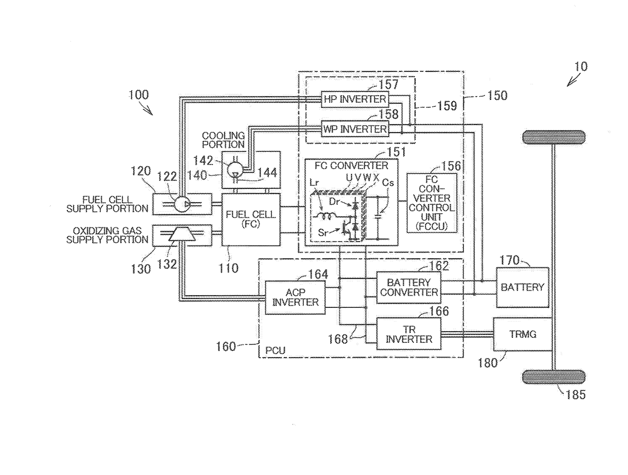
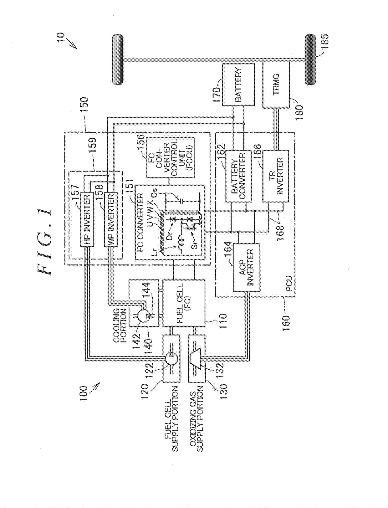
[0019]FIG. 1 is a schematic view of a structure of a fuel cell vehicle 10 in which a fuel cell system 100 is mounted in an embodiment of the disclosure. The fuel cell vehicle 10 includes a fuel cell (also referred to as an “PC”) HO, a fuel gas supply portion 120, an oxidizing gas supply portion 130, a cooling portion 140, an FC power supply unit 150, a power control unit 160, a battery 170, a traction motor (also referred to as a “TRMG”) 180, and wheels 185. In addition to the above components, the fuel cell vehicle 10 includes various devices included in, for example, in the fuel cell system. The various devices include auxiliary equipment, various sensors, various detectors, relays, and electronic devices. However, in this example, illustration and explanation of them are omitted.

[0020]The FC power supply unit 150 includes an FC converter 151, an FC converter control unit 156, and an inverter unit 159. The inverter unit 159 includes an HP inverter 157 and a WP inverter 158. The PC...


PUM

PropertyMeasurementUnit
heightaaaaaaaaaa
output voltageaaaaaaaaaa
temperatureaaaaaaaaaa

Abstract

A reactor unit includes reactors; and a cooler. The reactors are disposed in at least one line on a reactor cooling surface that is one of outer surfaces of the cooler. The cooler has a cooling medium flow passage that is in contact with an inner surface on a reverse side of the reactor cooling surface. The cooling medium flows linearly from an inlet portion to an outlet portion of the cooling medium flow passage. A direction in which the cooling medium flows inside the cooling medium flow passage is same as a direction in which the reactors are disposed in the at least one line. Cooling fins are provided on the inner surface on the reverse side of the reactor cooling surface. A longitudinal direction of each cooling fin is same as the direction in which the cooling medium flows inside the cooling medium flow passage.

Description

INCORPORATION BY REFERENCE[0001]The disclosure of Japanese Patent Application No. 2016-033972 filed on Feb. 25, 2016 including the specification, drawings and abstract is incorporated herein by reference in its entirety.BACKGROUND[0002]1. Technical Field[0003]The disclosure relates to a reactor unit and a fuel cell vehicle including the reactor unit.[0004]2. Description of Related Art[0005]Japanese Patent Application Publication No. 2013-244759 (JP 2013-244759 A) describes that a converter including a reactor portion (also referred to as a “reactor unit”) is used as a DC-DC converter that converts output voltage of a fuel cell in a fuel cell system mounted in a fuel cell vehicle. The reactor unit includes a plurality of reactors, and the plurality of reactors are disposed on two levels, which are upper and lower levels. On each of the levels, the plurality of reactors are disposed in a line in the front-rear direction of the fuel cell vehicle.SUMMARY[0006]However, when the above-men...

Claims


Application Information

Patent Timeline
Patent Type & Authority Applications(United States)
IPC IPC(8): H05K7/20B60K11/02H01M8/04029B60L11/18H01F27/08H02M3/155
CPCH05K7/20845H01F27/08H02M3/155H01M8/04029B60Y2400/202B60L11/1883B60K11/02H01M2250/20B60L2210/10B60L11/1892H01M10/613H01M10/625H01M10/6551H01M10/6567H01M2010/4271H01F27/10H01F37/00H01M8/04201B60K1/00B60K1/04B60K2001/001B60K2001/003B60K2001/005B60Y2400/61B60L50/72B60L58/33Y02T90/40Y02E60/50Y02E60/10
Inventor NAKAMURA, IKUHIROKAWAMURA, SHUJIMATSUURA, KOZOKATANO, KOJISEKINE, HIROYUKI
Owner TOYOTA JIDOSHA KK
Why Eureka
Try Eureka