Small flexible liquid core catheter for laser ablation in body lumens and methods for use

a liquid core catheter and flexible technology, applied in the field of small flexible liquid core catheters for laser ablation in body lumens and methods for use, can solve the problems of large size, low cutting area, high cost of pure silica optical fibers, etc., and design may not be scalable to a smaller flexible design for use as a disposable catheter, and design may not be adaptable to smaller flexible embodiments

Active Publication Date: 2017-09-21
RA MEDICAL SYST
View PDF0 Cites 6 Cited by
  • Summary
  • Abstract
  • Description
  • Claims
  • Application Information

AI Technical Summary

Benefits of technology

[0009]Some embodiments of a support catheter for use supporting a liquid core ablation catheter may include an inner tubular layer that may be less than about 0.001 inches in thickness, a thin over layer with of a material with a higher durometer than the inner tubular layer, a braided layer disposed over an outer surface of the inner tubular layer, and an outer layer covering the braided layer. In some cases, the support catheter may also have a wall thickness of less than about 0.006 inches. For some such embodiments, the support catheter may include an inner lumen with an inner diameter which is configured to accommodate passage of a liquid core ablation catheter and space therebetween sufficient for saline injection to flush blood and contrast fluid in front of the ablation catheter distal end. For some embodiments, the inner tubular layer of this catheter may include a low friction material to ease passage of the ablation catheter and may also include the requisite torqueability, pushability and kink resistance to guide an ablation catheter with a low enough profile to advance through an opening generated by such laser ablation of tissue with the ablation catheter. Some support catheter embodiments may include a multi-lumen support catheter, having one or more guidewire lumens, such as 2, 3, 4 or more guidewire lumens, and a working lumen configured for passage of an ablation catheter.
[0016]Some embodiments of a liquid core ablation catheter package assembly include a thin walled hermetically sealed enclosure having an interior volume and a material suitable for gamma sterilization. The package also includes a liquid core ablation catheter disposed within the interior volume of the hermetically sealed enclosure and a liquid disposed within the interior volume which is configured to maintain a vapor pressure within the interior volume sufficient to prevent loss of a liquid of a liquid core of the liquid core ablation catheter due to diffusion of the liquid core into the interior volume.
[0017]Some embodiments of an ablation catheter include an elongate catheter body, a transmissive core which is configured to transmit high energy laser light and which extends longitudinally from a proximal end to a distal end of the elongate catheter body, and an input surface in optical communication with the transmissive core at a proximal end of the elongate catheter body. The ablation catheter may also include an output surface in optical communication with the transmissive core at a distal end of the elongate catheter body. The ablation catheter may also have a tapered metal housing which includes a distal end having an inner bore that is disposed about the output surface, which includes a distal end that is longitudinally coextensive with a distal end of the output surface, which includes a tapered distal section that terminates distally with a thin wall that facilitates passage of a distal end of the ablation catheter through a lumen within a patient's body and which is configured to be sufficiently radiopaque in such as to be viewable by fluoroscopic imaging during a medical procedure.

Problems solved by technology

These pure silica optical fibers are expensive and have a low percentage of cutting area due to the clad and buffer used on the outside of the light conducting or transmissive core as well as a low density packing factor for the multiple fibers having a circular transverse cross section disposed in a bundle.
Such designs may be robust for repeated use but are large in size and may not be scalable to a smaller more flexible design for use as a disposable catheter in tortuous vessels such as a patient's vasculature.
Such designs may also not be adaptable to smaller more flexible embodiments to be used with a high pulse power and high pulse energy laser such as the ultraviolet excimer laser, particularly the 308 nm XeCl excimer.
Also, many of the previously disclosed fluids used for the transmissive core of these fluid core waveguides may not be suitably biocompatible for use inside the human body.

Method used


Image

  • Small flexible liquid core catheter for laser ablation in body lumens and methods for use
  • Small flexible liquid core catheter for laser ablation in body lumens and methods for use
  • Small flexible liquid core catheter for laser ablation in body lumens and methods for use

Examples


embodiment 8

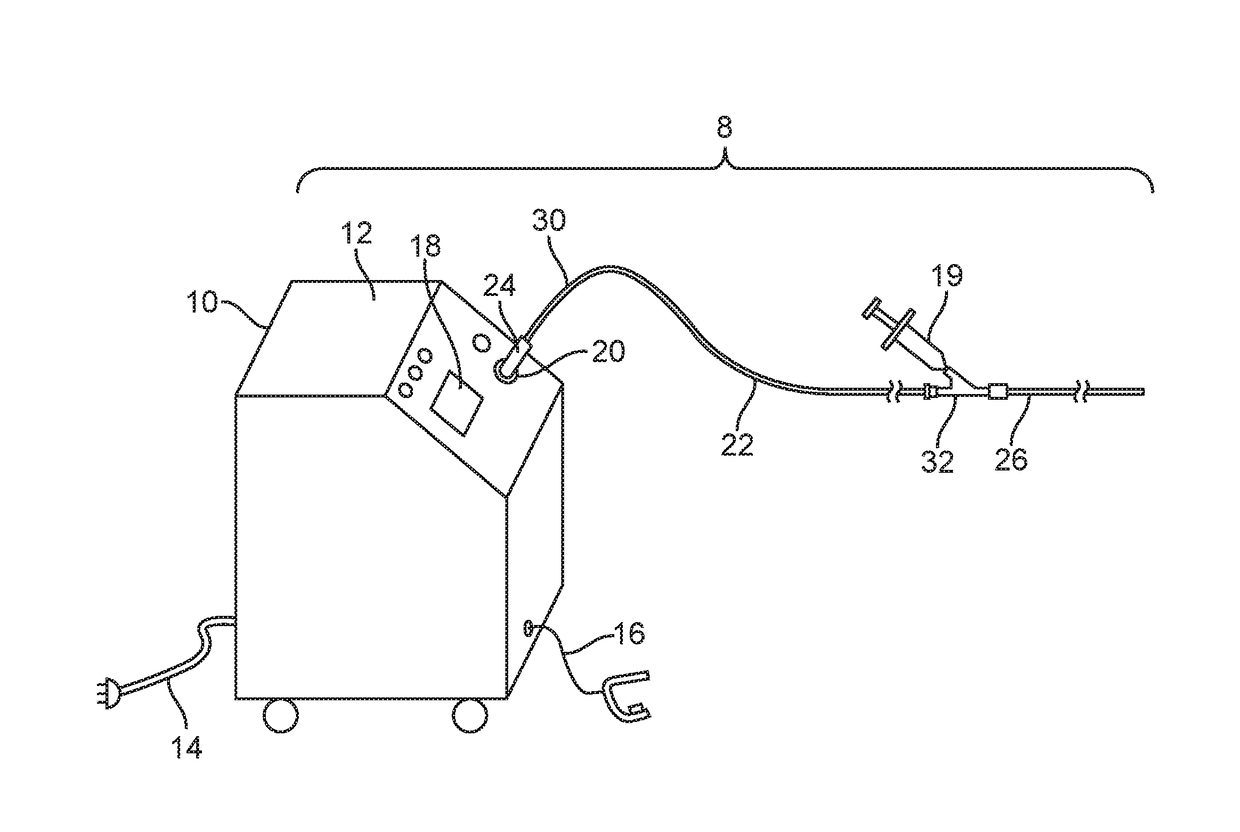
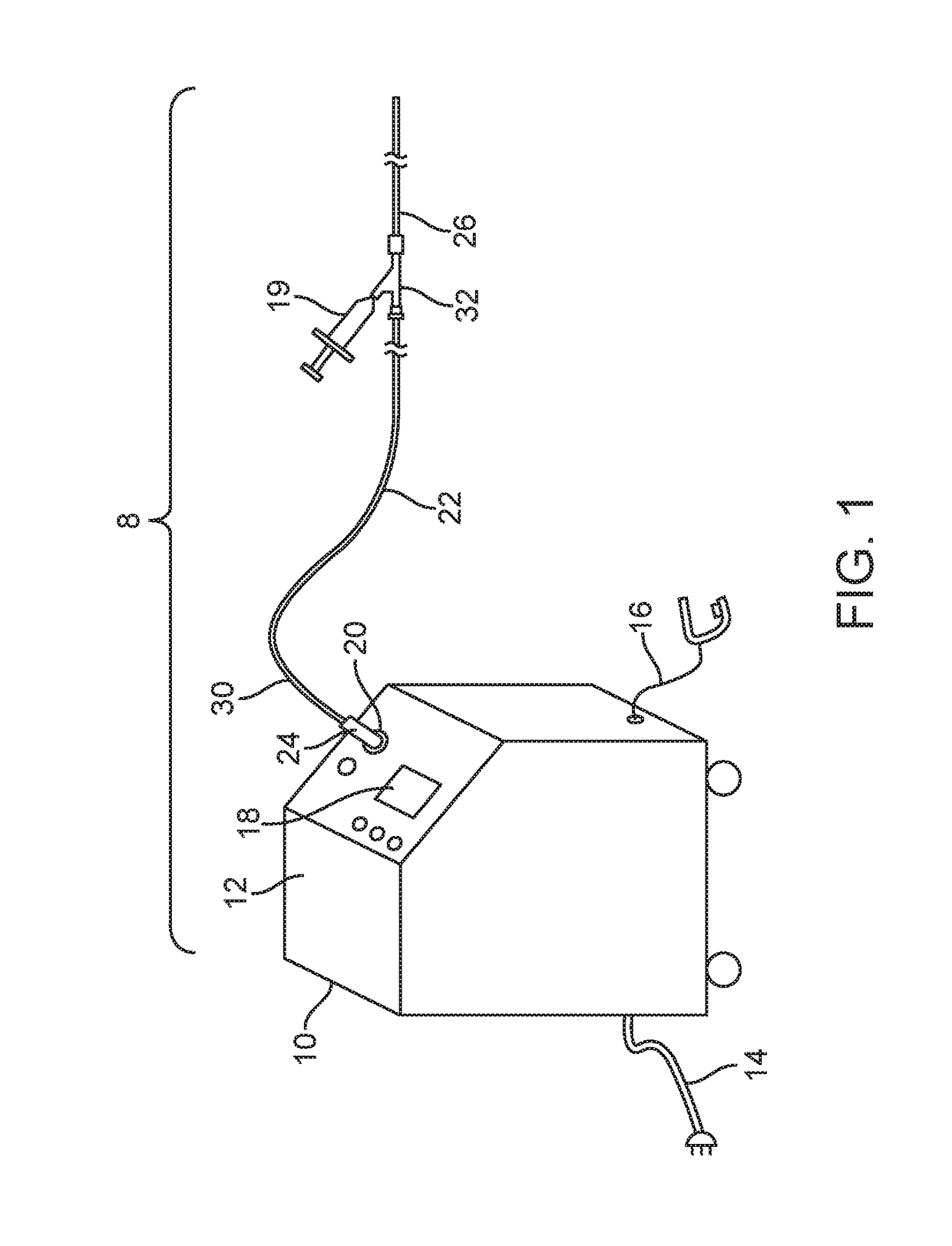
[0062]FIGS. 1-27 show a laser ablation system embodiment 8 that includes a laser energy source 10 including a housing 12, a power cord 14, an activation footswitch 16, a control panel 18 and an output coupler 20. A liquid core ablation catheter 22 has a laser coupler 24 which is disposed at a proximal end 30 of the ablation catheter 22 and which is coupled to the output coupler 20 of the laser source 10. The ablation catheter 22 is disposed within an inner lumen 28 (as shown in FIG. 18) of a support catheter 26 which may be used to guide or support the ablation catheter 22 within a body lumen of a patient. The support catheter 26 includes a Y-adapter 32 coupled to a proximal end 30 thereof. The liquid core ablation catheter 22 is disposed within and passes through a central lumen (not shown) of the Y-adapter 32 as well. The support catheter 26 and ablation catheter 22 each may have a radiopaque marker 31 disposed at a respective distal end thereof. A working length of the liquid cor...

embodiment 22

[0080]Another disadvantage with using an FEP tube liner may be that the hardness shore durometer of about 55 D is about half that of PCTFE which may have a shore hardness of about 85 D to about 95 D. When the FEP liner is thin and has a low durometer then there may be an impression of thin elements of a braid material 52 used on an outside surface 68 (shown in FIG. 14) of a base tube 50 of the multi-layer catheter tube 38 to transfer into the inner luminal surface 64 of the inner luminal layer 48 which may cause the light to be scattered out of the tube. Also, when an ablation catheter 22 is placed in the Y adapter 32 and a corresponding hemostatic valve thereof, the valve may compresses a low durometer ablation catheter embodiment 22, distort the wall structure of the ablation catheter and hinder transmission of light therethrough.

[0081]We have found that polychlorotrifluoroethylene, PCTFE, has one of the lowest diffusion rates for water compared to other polymer plastics, and can ...

embodiment 38

[0088]Other methods for forming such a low index layer from these materials may include extruding a thin layer, for example, of solid Teflon AF 2400® or Teflon AF 1601®, over a smooth polished metal mandrel to form the inner luminal layer 48 of the multi-layer catheter tube 38 of the liquid core ablation catheter 22. In some cases, such an extruded thin layer of low index material may have a thickness of about 5 microns to about 50 microns. Once the amorphous fluoropolymer inner luminal layer 48 is extruded over the mandrel, the outer surface 76 (shown in FIG. 14) of the inner luminal layer 48 may then be etched to promote surface adhesion thereto. A thicker wall PCTFE base layer tube 50, or base layer tube 50 made from another suitable material, such as FEP, may then be over extruded onto the etched outer surface 76 of the inner luminal layer 48, followed by braiding of a multi-filament braid 52 over the outer surface of the PCTFE tube 50. Then an over-jacket 54 may be extruded ove...


PUM

PropertyMeasurementUnit
thicknessaaaaaaaaaa
lengthaaaaaaaaaa
lengthaaaaaaaaaa

Abstract

Embodiments relate to the design and use of a low profile ablation catheter with a liquid core for use in laser ablation removal of arterial plaque blockages to restore blood flow.

Description

RELATED APPLICATIONS[0001]This application is a divisional application of U.S. patent application Ser. No. 13 / 651,070, filed Oct. 12, 2012, entitled Small Flexible Liquid Core Catheter for Laser Ablation in Body Lumens and Methods for Use, by J. Laudenslager et al., which claims priority under 35 USC 119(e) from U.S. Provisional Patent Application No. 61 / 547,435, filed Oct. 14, 2011, entitled Small Flexible Liquid Core Catheter for Laser Ablation and Method for Use, by J. Laudenslager et al., the entirety of each of the aforementioned patent applications is incorporated by reference herein.BACKGROUND[0002]Laser catheters and laser delivery systems in general have wide range of applications in the medical field. Such systems may be used to deliver laser energy to desired sites of a patient's anatomy, and may be particularly suitable for delivering laser energy to locations within a patient's body that allow for minimally invasive treatment of a variety of indications using a variety ...

Claims


Application Information

Patent Timeline
Patent Type & Authority Applications(United States)
IPC IPC(8): A61L29/04A61L29/14A61L29/08
CPCA61L29/041A61L29/08A61L29/085A61L29/14A61B18/24A61B18/245A61B2090/3966A61B2018/2025A61M25/0009A61B2018/206C08L27/12
Inventor LAUDENSLAGER, JAMES B.IRWIN, DEAN S.DIAZ, CESAR
Owner RA MEDICAL SYST
Why Eureka
Try Eureka