Highly Linear, Highly Efficient Wideband RF Power Amplifier Having Wide Video Bandwidth Capability

a power amplifier and wideband technology, applied in the field of radio frequency power amplifiers, can solve the problems of insufficient wideband video bandwidth capability, and inability to design an rf pa that is both highly linear and highly efficient, and achieves wide operating bandwidth, high back-off conversion efficiency, and insensitivity. the effect of high efficiency

Active Publication Date: 2017-09-21
TECH UNIV DELFT
View PDF0 Cites 6 Cited by
  • Summary
  • Abstract
  • Description
  • Claims
  • Application Information

AI Technical Summary

Benefits of technology

[0016]The RF PA apparatus of the present invention has a number of significant performance advantages over prior art RF PA approaches. First, it is able to realize conversion efficiencies at backed-off power levels that are comparable to, and in some cases even exceeding, the backed-off conversion efficiencies realized by a conventional Doherty RF PA apparatus. This capability, along with its inherent insensitivity to changing antenna impedances, make the RF PA apparatus of the present invention well-suited for multicarrier applications such as, for example, the carrier aggregation approach contemplated in the Long Term Evolution Advanced (LTE-A) mobile communications standard. Second, it is capable of operating with high back-off conversion efficiencies over a wide range of operating frequencies. Unlike the Doherty RF PA, the RF PA apparatus of the present invention does not rely on the principle of load modulation. Consequently, the tuning bandwidth of the RF PA apparatus of the present invention is not restricted as it is in the Doherty RF PA. Third, not only does the RF PA apparatus of the present invention have a wide operating bandwidth, it also has a wider video bandwidth than can be realized in envelope tracking RF PAs since the RF PA apparatus of the present invention does not employ a dynamic power supply (DPS). Finally, the spurious emissions problem that plagues Class-G RF PAs is completely avoided since the power supply voltages to the first and second RF PAs of the RF PA apparatus remain constant at all times and are not switched. The gradual handoff capability of the RF PA apparatus can also be exploited to reduce the possibility of spurious emission generation during handoff events. Compliance with strict spectral mask requirements is consequently much easier to satisfy than for Class-G RF PAs. The RF PA apparatus of the present invention is therefore an excellent candidate for high-PAPR wideband applications in which high linearity, high conversion efficiency, and wide video bandwidth capability are all desired.

Problems solved by technology

Unfortunately, due to physical limitations of the power transistors that make up RF PAs and how the power transistors operate, designing an RF PA that is both highly linear and highly efficient is very difficult.
Designing an RF PA that is capable of operating with high linearity and high efficiency at a specific frequency or over a narrow range of frequencies is difficult by itself.
Designing an RF PA that is capable of operating with high linearity and high efficiency over a wide range of operating frequencies and which also has a wide video bandwidth capability is even more, in fact is considerably more, difficult.
However, unfortunately, it is also highly inefficient.
Unfortunately, this requirement undesirably results in the power transistor 102 dissipating large amounts of quiescent power.
This low conversion efficiency is highly undesirable, particularly in circumstances where the power supply is a battery, such as in a wireless handset, for example, since the low conversion efficiency substantially limits the charge life of the battery.
One consequence of biasing the RF PA at the boundary of the active and cutoff regions, however, is that the RF PA then only becomes capable of amplifying the positive portions of the RF input.
Unfortunately, this back-off requirement can substantially limit the realizable conversion efficiency of the Class-B RF PA 600, especially in circumstances where the PAPR is high.
Although the Doherty RF PA 1000 is able to increase conversion efficiencies at backed-off power levels over that which can be realized in the conventional Class-B RF PA 600, it has a number of significant limitations.
First, the impedance inverters 1008 and 1010 and impedance transformer 1012 are frequency dependent and consequently limit the possible tuning bandwidth of the Doherty RF PA 1000.
These frequency dependent constraints are a significant problem since many modern and evolving communications standards require an RF PA with a tuning bandwidth up to, and in some cases exceeding, 100 MHz.
The conventional Doherty RF PA 1000 does not provide this tuning bandwidth capability.
This sensitivity is a severe problem when applied in mobile handsets, where the effective antenna impedance is influenced by the changing operating environment.
Additionally, this load sensitivity of the Doherty RF PA 1000 is problematic in applications intended to support carrier aggregation techniques, such as in the LTE Advanced (LTE-A) mobile communications standard.
In such applications some kind of antenna impedance control to handle the total composite signal over the band can have a dramatic impact on the handling of the individual signals yielding undesirable distortion.
Although this rail switching approach can help to improve conversion efficiencies at backed-off power levels, the hard switching of the power supplies yields spurious emissions that are very difficult to correct for.
Although the ET RF PA 1400 is highly efficient, one significant limitation associated with its use relates to the DPS 1402.
The reason for the difficulty is that the power transistors that make up the DPS 1402 have practical constraints that limit their ability to react quickly to rapidly changing signal envelopes, especially in circumstances where the PAPR of the signal envelope is high and the magnitude of the signal envelope approaches zero.
When the envelope signal bandwidth exceeds the ability of the power transistors to react, significant amplitude distortion results.

Method used


Image

  • Highly Linear, Highly Efficient Wideband RF Power Amplifier Having Wide Video Bandwidth Capability
  • Highly Linear, Highly Efficient Wideband RF Power Amplifier Having Wide Video Bandwidth Capability
  • Highly Linear, Highly Efficient Wideband RF Power Amplifier Having Wide Video Bandwidth Capability

Examples


Embodiment Construction

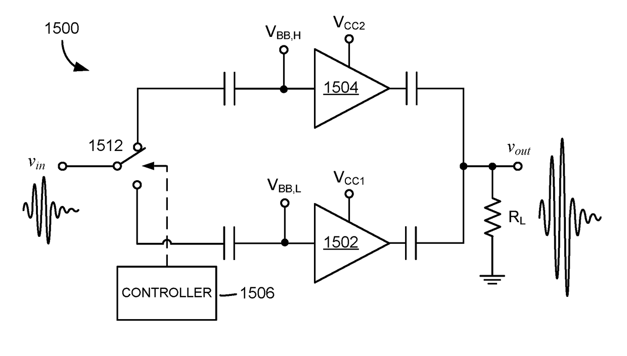
[0053]Referring to FIG. 15, there is shown a radio frequency power amplifier (RF PA) apparatus 1500, according to one embodiment of the present invention. The RF PA apparatus 1500 comprises a low-power RF PA 1502, a high-power RF PA 1504, and a controller 1506. The low-power RF PA 1502 and high-power RF PA 1504 may be constructed using either bipolar junction power transistors (BJTs) or field-effect power transistors (FETs). Further, to support high-power, high-frequency applications, any high-power, high-frequency power transistor technology may be used, including, for example, gallium-arsenide (GaAs) metal-semiconductor FETs (MESFETs), gallium-nitride (GaN) high electron mobility transistors (HEMTs), laterally-diffused metal-oxide-semiconductor (LDMOS) transistors, high-breakdown-voltage transistors using silicon-on-insulator (SOI) technology, high-power heterojunction bipolar junction (HBTs), etc. In the detailed description that follows, it is assumed for purposes of illustratio...


PUM


Abstract

A radio frequency power amplifier (RF PA) apparatus includes a first RF PA, a second RF PA, and a controller. The first RF PA is configured to deliver RF power to a load over a first range of RF power levels. The second RF PA is configured to deliver RF power to the load over a second range of RF power levels greater than the first range of RF power levels. The controller controls whether the first RF PA is delivering RF power to the load or the second RF PA is delivering RF power to the load, and is further configured to coordinate and control handoffs between the first and second RF PAs by varying magnitudes of input RF voltages applied to the RF input ports of the first and second RF PAs or by varying magnitudes of input bias voltages applied to the RF input ports of the first and second RF PAs.

Description

FIELD OF THE INVENTION[0001]The present invention relates to radio frequency power amplifiers (RF PAs).BACKGROUND OF THE INVENTION[0002]Two principal goals normally involved in the design of a radio frequency (RF) transmitter are linearity and efficiency. These goals are substantially impacted by the design and operation of the RF transmitter's power amplifier (RF PA). RF PA linearity refers to how capable the RF PA is at producing a linear reproduction of the RF signal applied to its input. RF PA efficiency refers to how energy efficient the RF PA is at converting power supplied to it from its power supply into RF power. Unfortunately, due to physical limitations of the power transistors that make up RF PAs and how the power transistors operate, designing an RF PA that is both highly linear and highly efficient is very difficult.[0003]A third goal often involved in the design of an RF PA is to make the RF PA so that it is capable of operating over a wide range of frequencies and ha...

Claims


Application Information

Patent Timeline
Patent Type & Authority Applications(United States)
IPC IPC(8): H03F1/02H03F3/21H03F3/19
CPCH03F1/0288H03F3/19H03F2200/451H03F2200/36H03F3/21H03F1/025H03F1/0277H03F3/211H03F3/72H03F2200/102H03F2200/321H03F2200/516H03F2203/21106H03F2203/21109H03F2203/21131H03F2203/21142H03F2203/21145H03F2203/21154H03F2203/7236H03F1/0266
Inventor DE VREEDE, LEONARDUS C.N.MCCUNE, JR., EARL W.
Owner TECH UNIV DELFT
Why Eureka
Try Eureka