Electrically conductive fine particles

a technology of electric conductive fine particles and fine particles, applied in the direction of metal/alloy conductors, conductors, conductors, etc., can solve the problem that the paste covered by the mask is not cured, and achieve the effect of high thermal conductivity during heating, good printing characteristics, and successful sinting

Inactive Publication Date: 2017-11-16
TOKUSEN IND CO LTD
View PDF10 Cites 1 Cited by
  • Summary
  • Abstract
  • Description
  • Claims
  • Application Information

AI Technical Summary

Benefits of technology

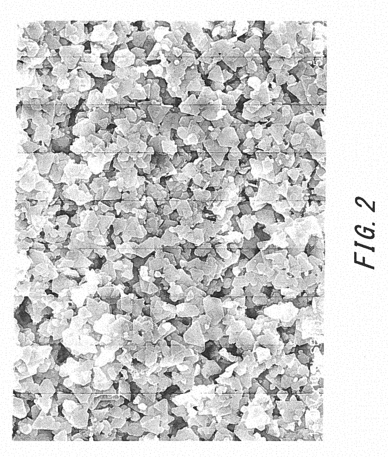
[0020]The particles according to the present invention include the large number of fine particles. The fine particles are extremely small. In a paste, the fine particles disperse sufficiently. The paste containing the fine particles has good printing characteristics.
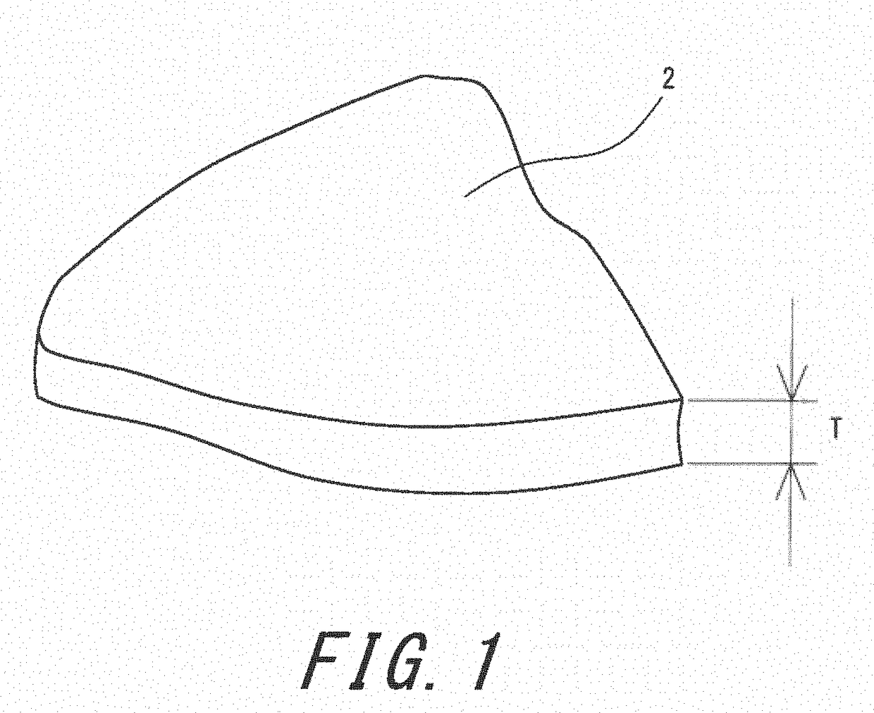
[0021]Since the fine particles are flake-like, the fine particles overlap each other with a large contact surface area in the paste after printing. Therefore, the paste exhibits high thermal conductivity during heating. The paste can be successfully sintered by heating for a short time. The paste can be successfully sintered by heating at low temperature.
[0022]In a pattern after sintering, the fine particles overlap each other with a large contact surface area. Therefore, the pattern easily conducts electricity. The fine particles also have good electrical conductivity.

Problems solved by technology

The paste covered by the mask is not cured.

Method used


Image

  • Electrically conductive fine particles
  • Electrically conductive fine particles
  • Electrically conductive fine particles

Examples


example 1

[0068]Fifty grams of silver nitrate was dissolved in 1 L of distilled water to obtain a first solution. Meanwhile, 22.2 g of oxalic acid was dissolved in 1 L of distilled water to obtain a second solution. The first solution was mixed with the second solution to obtain a mixture liquid containing silver oxalate. Impurities were removed from this mixture liquid. Three grams of polyethylene glycol (dispersant) was added to 1 L of the mixture liquid, and the mixture liquid was stirred for 30 minutes while ultrasonic waves were applied thereto. With this, silver oxalate was dispersed. An appropriate amount of acetic acid was added to the dispersion liquid to adjust the PH of the dispersion liquid to 3. The dispersion liquid was placed in an autoclave. The dispersion liquid was pressurized at a pressure of 0.5 MPa. The dispersion liquid was heated to 130° C. while being stirred at a speed of 300 rpm. The stirring was conducted for 30 minutes at this temperature to obtain a liquid contain...

example 2

[0069]A liquid containing fine particles was obtained in the same manner as Example 1, except formic acid was added to the dispersion liquid instead of acetic acid to adjust the PH to 4, the temperature of the dispersion liquid was set to 150° C., and the stirring speed was set to 350 rpm.

example 3

[0070]A liquid containing fine particles was obtained in the same manner as Example 1, except propionic acid was added to the dispersion liquid instead of acetic acid to adjust the PH to 5, pressure was not applied before the reaction, and the temperature during the reaction was set to 150° C.


PUM

PropertyMeasurementUnit
particle size distribution measurementaaaaaaaaaa
particle diameter Dmaxaaaaaaaaaa

Abstract

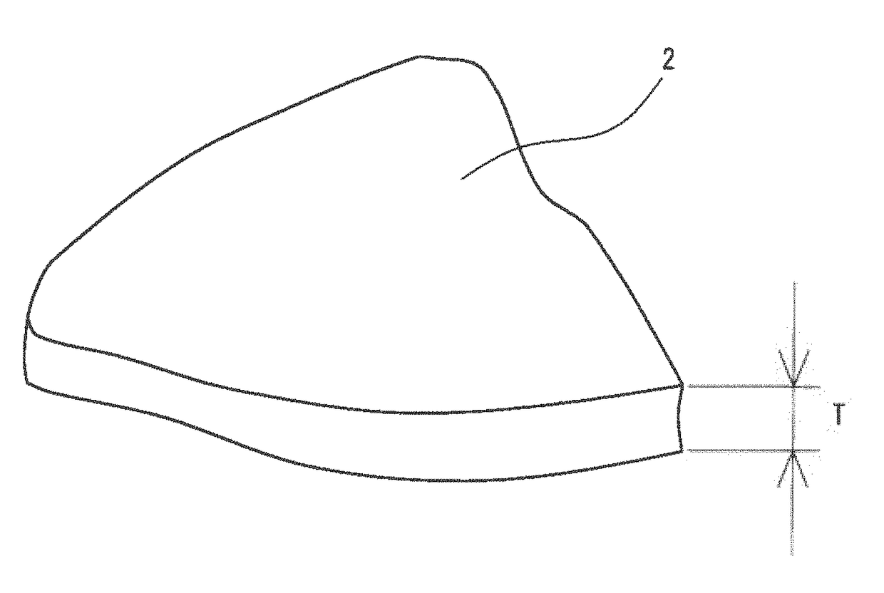
[Object] To provide fine particles 2 having good printing characteristics, good thermal conductivity, and good electrical conductivity.
[Solution] The fine particles 2 are flake-like. A main component of the fine particles 2 is an electrically conductive metal. A typical metal is silver. A particle diameter D50 of particles including a large number of the fine particles 2 is equal to or greater than 0.10 μm but equal to or less than 0.50 μm, a particle diameter D95 of the particles is equal to or less than 1.00 μm, and a maximum particle diameter Dmax of the particles is equal to or less than 3.00 μm. A particle diameter D10 of the particles is equal to or greater than 0.05 μm. A BET specific surface area of the particles is equal to or greater than 2.0 m2/g. A tap density TD of the particles is equal to or greater than 2.0 g/cm3. An average Tave of thicknesses of the fine particles 2 is equal to or less than 0.05 μm.

Description

TECHNICAL FIELD[0001]The present invention relates to electrically conductive fine particles. Specifically, the present invention relates to fine particles that are flake-like and of which a main component is a metal.BACKGROUND ART[0002]An electrically conductive paste is used for the production of printed circuit boards for electronic devices. The paste contains: fine particles of which a main component is a metal; a binder; and a liquid organic compound (solvent). By using the paste, a pattern of wiring that connects electronic components to each other is printed. After the printing, the paste is heated. By the heating, fine metal particles are sintered with fine metal particles adjacent thereto.[0003]JP2007-254845 discloses particles of which a material is silver and that are flake-like. The particles are formed by processing spherical fine particles with a bead mill.[0004]As a method for printing a pattern, an etching method, a squeegee method, and an inkjet method are adopted.[...

Claims


Application Information

Patent Timeline
Patent Type & Authority Applications(United States)
IPC IPC(8): B22F1/00H01B1/22B22F9/24B22F9/30H05K3/32H01B1/02B22F1/068B22F1/102B22F1/107
CPCB22F1/0055H05K3/321B22F9/24B22F1/0074B22F9/30H01B1/02H01B1/22B22F2301/255B22F1/00B22F9/00H01B5/00B22F1/107B22F1/068B22F1/102B22F2301/10
Inventor LEE, WOOJINWAKASAKI, SHUNKANAMORI, TAKAYUKI
Owner TOKUSEN IND CO LTD
Why Eureka
Try Eureka