Cavo-arterial pump

a technology of cavo and valve, applied in the field of cavo valve, can solve the problems of limited the effectiveness of mechanical circulatory support therapy in heart failure patients, limited the effectiveness of mcs therapy, and the development of right ventricular assist devices (rvads) has lagged significantly compared to lvad technology

Inactive Publication Date: 2017-11-30
YALE UNIV
View PDF1 Cites 33 Cited by
  • Summary
  • Abstract
  • Description
  • Claims
  • Application Information

AI Technical Summary

Problems solved by technology

Right ventricular (RV) dysfunction due to pulmonary hypertension, acute myocardial infarction, and left ventricular assist device-induced hemodynamic changes has limited the effectiveness of mechanical circulatory support therapy in heart failure patients.
However, LVAD-induced right heart dysfunction is a problem that has limited the effectiveness of MCS therapy in the HF population (Dang et al., J Heart Lung Transplant.
Despite the potential of RVAD therapy, the development of right ventricular assist devices (RVADs) has lagged significantly compared to LVAD technology.
Despite this potential paradigm shift in RV dysfunction therapy, percutaneous pump technology is still limited to short-term use (a few hours) because of the need for a driveline to power the device and the need for purge sealing system that cools the pump motor and provides a seal between the motor-shaft and impeller interface (Butler et al., IEEE Trans Biomed Eng. 1990, 37(2):193-196; Rosarius et al., Artif Organs.
Together, the purging fluid line and driveline exit the patient's vasculature and limits patient mobility.

Method used


Image

  • Cavo-arterial pump
  • Cavo-arterial pump
  • Cavo-arterial pump

Examples


experimental examples

[0051]The invention is further described in detail by reference to the following experimental examples. These examples are provided for purposes of illustration only, and are not intended to be limiting unless otherwise specified. Thus, the invention should in no way be construed as being limited to the following examples, but rather, should be construed to encompass any and all variations which become evident as a result of the teaching provided herein.

[0052]Without further description, it is believed that one of ordinary skill in the art can, using the preceding description and the following illustrative examples, make and utilize the present invention and practice the claimed methods. The following working examples therefore, specifically point out the preferred embodiments of the present invention, and are not to be construed as limiting in any way the remainder of the disclosure.

example 1

n and Fabrication

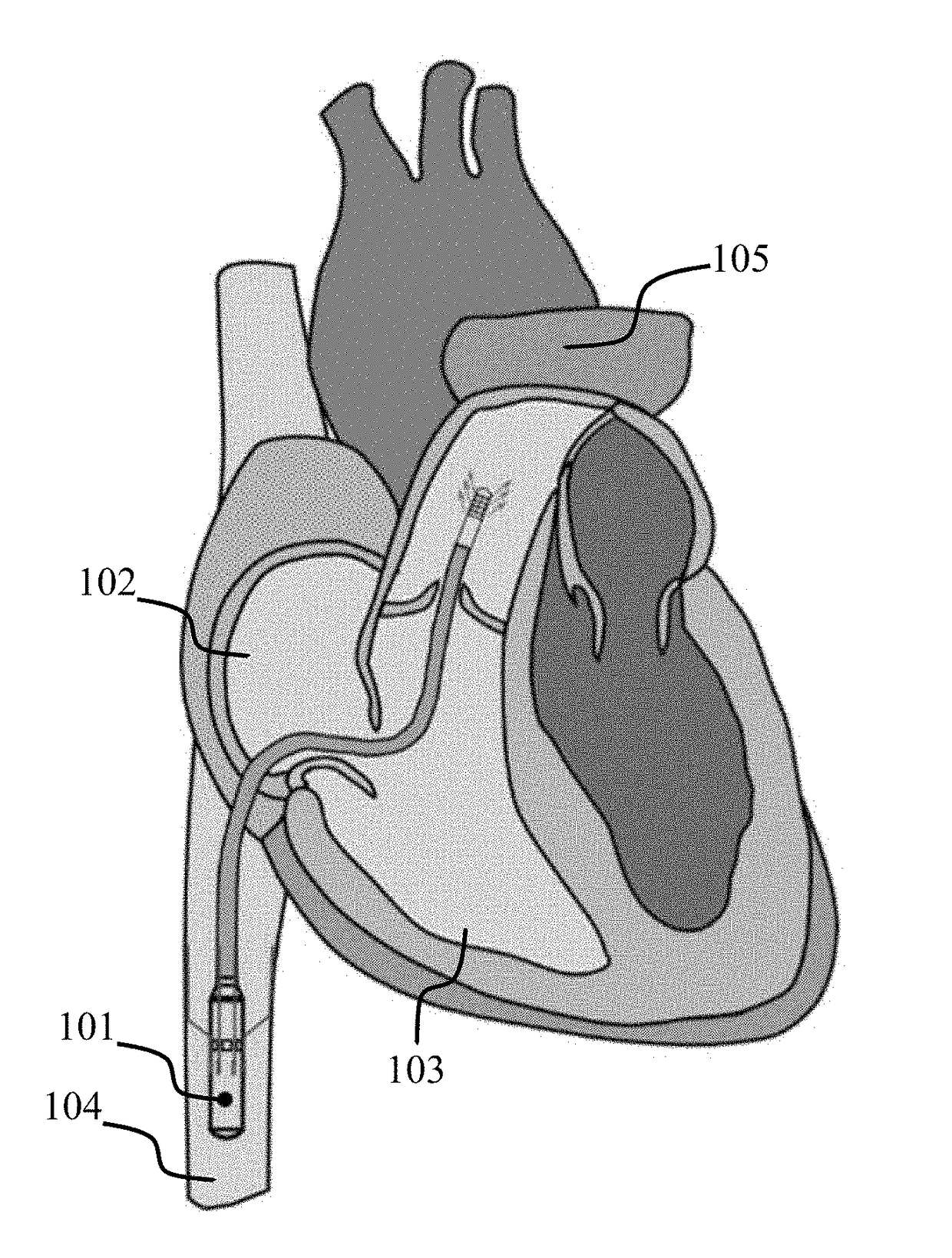
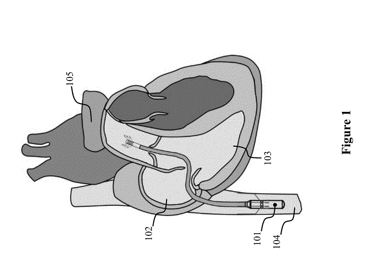
[0053]The intravascular pump designed is intended to provide partial circulatory support (2.5-3 L / min) to patients with LVAD-induced right ventricular dysfunction. The intravascular pump 101, which is called the cavo-arterial pump (CAP), would sit in the inferior vena cava 104 and propel venous blood to the main pulmonary artery 105 (FIG. 1). Preliminary sizing of the pump impeller and speed of operation were determined by a combination of fabrication tolerances and the general design criteria for turbomachinery (Stepanoff, Centrifugal and Axial Flow Pumps: Theory, Design, and Application. Krieger Publishing Company; 1957). In this design iteration, the CAP was designed to produce 2.5 L / min against at 30 mm Hg pressure head for right ventricular support. The impeller diameter was set to 7.5 mm. The specific work of this pump was calculated using:

y=ΔPρ(Equation1)

where y is the specific work, ΔP is the pressure head across the pump, and p is the density of blood. The ...

example 2

ive CAP

[0062]The direct drive CAP was tested on a bench-top flow loop to test the performance. The flow loop, shown in FIG. 5, consists of a reservoir 501, flexible tubing 502, and a submersion tank 503 for pump 504. Reusable blood pressure transducers 505 and 506, MLT0380, (AD Instruments, Dunedin, New Zealand) were used to measure the tank pressure and pump outlet pressure. An ultrasonic flow sensor, ME8PXL, and flow meter 507, TS410 (Transonic Systems Inc., Ithaca, N.Y., USA) were used to measure the pump flow rate. A gate valve located at the pump outlet was used to modulate the outlet resistance and increase afterload. Motor shaft speed was set with a sensorless motor drive (S48V5A, Koford Engineering LLC., Winchester, Ohio, USA) and external potentiometer. Two different working fluids were used. The first was water and the second was a 40% by volume glycerol and 60% by volume water solution to mimic the viscosity of blood. Viscosity was not specifically measured in these exper...


PUM


Abstract

The present invention provides an intravascular right ventricular assist device, i.e., the cavo-arterial pump (CAP). Two prototypes of the CAP were developed, including a direct drive CAP and a magnetic drive CAP, demonstrating the feasibility of providing adequate pulmonary support and the feasibility of using axial magnetic couplings for contactless torque transmission from the motor shaft to the pump impeller. The magnetic drive CAP was able to operate up to 18.5 kRPM and produce a maximum flow rate of 1.35 L / min and a maximum pressure head of 40 mm Hg.

Description

CROSS-REFERENCE TO RELATED APPLICATIONS[0001]This application claims priority to U.S. Provisional Patent Application No. 62 / 342,301, filed on May 27, 2016, the contents of which are incorporated by reference herein in its entirety.BACKGROUND OF THE INVENTION[0002]Right ventricular (RV) dysfunction due to pulmonary hypertension, acute myocardial infarction, and left ventricular assist device-induced hemodynamic changes has limited the effectiveness of mechanical circulatory support therapy in heart failure patients. Right ventricular (RV) dysfunction can result as a sequelae of pulmonary hypertension, myocardial infarction, and acute / chronic volume or pressure overload conditions. Mechanical circulatory support (MCS) devices, specifically left ventricular assist devices (LVADs), have extended the lives of many adults suffering from end-stage congestive heart failure (HF). However, LVAD-induced right heart dysfunction is a problem that has limited the effectiveness of MCS therapy in t...

Claims


Application Information

Patent Timeline
Patent Type & Authority Applications(United States)
IPC IPC(8): A61M1/10A61M1/36A61M1/12A61M25/00A61M60/13A61M60/174A61M60/216A61M60/411A61M60/419A61M60/546A61M60/554A61M60/82A61M60/825A61M60/861
CPCA61M1/1049A61M1/1046A61M1/3653A61M1/101A61M25/0068A61M25/0043A61M1/122A61M60/422A61M60/82A61M60/174A61M60/411A61M60/419A61M60/216A61M60/546A61M60/554A61M60/13A61M60/825A61M60/861
Inventor BONDE, PRAMODVALDOVINOS, JOHN
Owner YALE UNIV
Why Eureka
Try Eureka