Method and Device for Feedback Control of Neural Stimulation

a neural stimulation and feedback technology, applied in the field of neural stimulation feedback control, can solve the problems of reducing the therapeutic effect of scs, creating side effects including over-stimulation, and unwanted side effects

Active Publication Date: 2017-12-21
SALUDA MEDICAL PTY LTD
View PDF2 Cites 79 Cited by
  • Summary
  • Abstract
  • Description
  • Claims
  • Application Information

AI Technical Summary

Benefits of technology

[0037]In some such embodiments, an estimation unit may be provided which produces an estimate P′ of the slope P. The estimation P′ may in some embodiments be produced by the estimation unit from an empirical relationship of stimulus current to measured ECAP amplitude, and for example may be estimated as P′=(V+K) / I, where V is ECAP amplitude, K is a constant or function which relates P to a stimulus threshold T, for example K=P.T, and I is stimulus current amplitude. In such embodiments, the estimate P′ may then be introduced into the feedback loop to counteract the effect of P. For example, an error signal of the feedback loop may be scaled by 1 / P′.

Problems solved by technology

These changes in current result in changes to recruitment and paresthesia, which can reduce the therapeutic effect of SCS and can create side effects including over-stimulation.
In almost all neuromodulation applications, a single class of fibre response is desired, but the stimulus waveforms employed can recruit action potentials on other classes of fibres which cause unwanted side effects, such as muscle contraction if motor fibres are recruited.
The task of maintaining appropriate stimulus amplitude is made more difficult by electrode migration and / or postural changes of the implant recipient, either of which can significantly alter the neural recruitment arising from a given stimulus, depending on whether the stimulus is applied before or after the change in electrode position or user posture.
Postural changes alone can cause a comfortable and effective stimulus regime to become either ineffectual or painful.
Another control problem, facing neuromodulation systems of all types, is achieving neural recruitment at a sufficient level required for therapeutic effect, but at minimal expenditure of energy.
The power consumption of the stimulation paradigm has a direct effect on battery requirements which in turn affects the device's physical size and lifetime.
For rechargeable systems, increased power consumption results in more frequent charging and, given that batteries only permit a limited number of charging cycles, ultimately this reduces the implanted lifetime of the device.

Method used


Image

  • Method and Device for Feedback Control of Neural Stimulation
  • Method and Device for Feedback Control of Neural Stimulation
  • Method and Device for Feedback Control of Neural Stimulation

Examples


Embodiment Construction

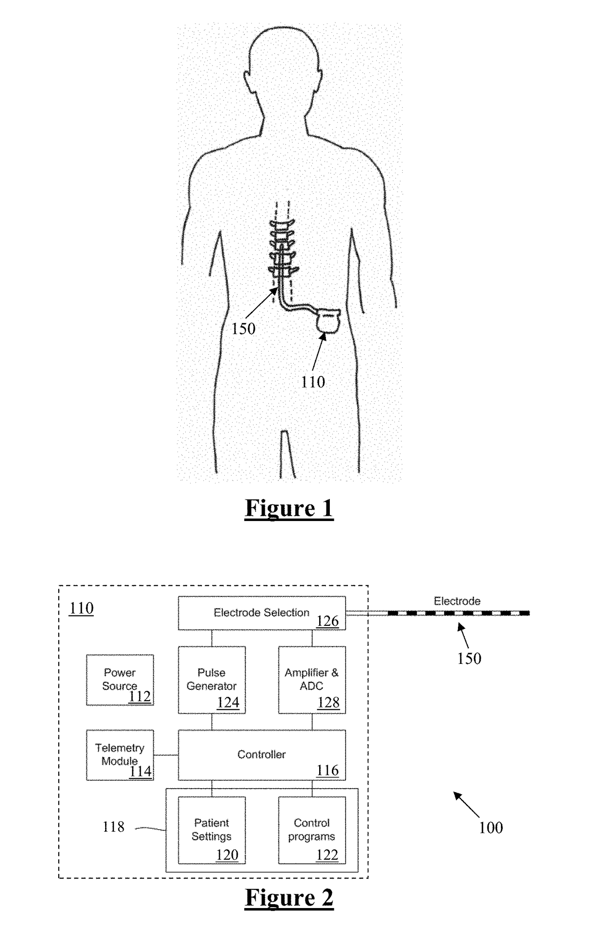
[0064]FIG. 1 schematically illustrates an implanted spinal cord stimulator 100. Stimulator 100 comprises an electronics module 110 implanted at a suitable location in the patient's lower abdominal area or posterior superior gluteal region, and an electrode assembly 150 implanted within the epidural space and connected to the module 110 by a suitable lead.

[0065]FIG. 2 is a block diagram of the implanted neurostimulator 100. Module 110 contains a battery 112 and a telemetry module 114. In embodiments of the present invention, any suitable type of transcutaneous communication, such as infrared (IR), electromagnetic, capacitive and inductive transfer, may be used by telemetry module 114 to transfer power and / or data between an external device and the electronics module 110.

[0066]Module controller 116 has an associated memory 118 storing patient settings 120, control programs 122 and the like. Controller 116 controls a pulse generator 124 to generate stimuli in the form of current pulses...


PUM


Abstract

A method of controlling a neural stimulus by use of feedback. The neural stimulus is applied to a neural pathway in order to give rise to an evoked action potential on the neural pathway. The stimulus is defined by at least one stimulus parameter. A neural compound action potential response evoked by the stimulus is measured. From the measured evoked response a feedback variable is derived. A feedback loop is completed by using the feedback variable to control the at least one stimulus parameter value. The feedback loop adaptively compensates for changes in a gain of the feedback loop caused by electrode movement relative to the neural pathway.

Description

Technical Field[0001]The present invention relates to controlling a neural response to a stimulus, and in particular relates to measurement of a compound action potential by using one or more electrodes implanted proximal to the neural pathway, in order to provide feedback to control subsequently applied stimuli.BACKGROUND OF THE INVENTION[0002]There are a range of situations in which it is desirable to apply neural stimuli in order to give rise to a compound action potential (CAP). For example, neuromodulation is used to treat a variety of disorders including chronic pain, Parkinson's disease, and migraine. A neuromodulation system applies an electrical pulse to tissue in order to generate a therapeutic effect. When used to relieve chronic pain, the electrical pulse is applied to the dorsal column (DC) of the spinal cord. Such a system typically comprises an implanted electrical pulse generator, and a power source such as a battery that may be rechargeable by transcutaneous inducti...

Claims


Application Information

Patent Timeline
Patent Type & Authority Applications(United States)
IPC IPC(8): A61N1/36A61N1/05
CPCA61N1/36139A61N1/36071A61N1/36062A61N1/0551
Inventor SINGLE, PETER SCOTT VALLACK
Owner SALUDA MEDICAL PTY LTD
Why Eureka
Try Eureka