

Grease composition for lubricating resins and electric power steering device
a technology of lubricating resin and electric power steering device, which is applied in the direction of gearing, gearing details, hoisting equipment, etc., can solve the problems of large backlash of gear provided with a rattling noise, and achieve excellent heat resistance, reduce steering torque, and high surface roughness
- Summary
- Abstract
- Description
- Claims
- Application Information
AI Technical Summary
Benefits of technology
Problems solved by technology
Method used
Image

Examples
first embodiment
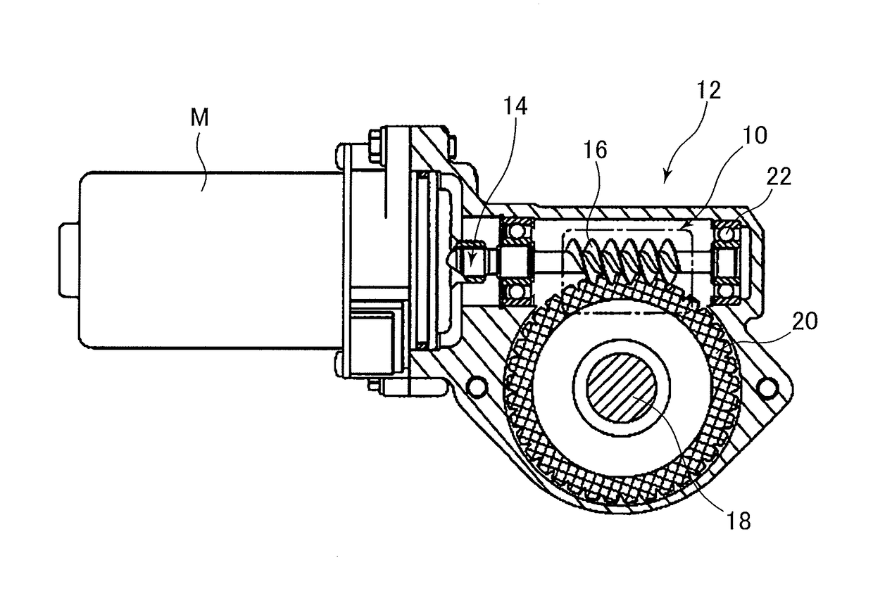
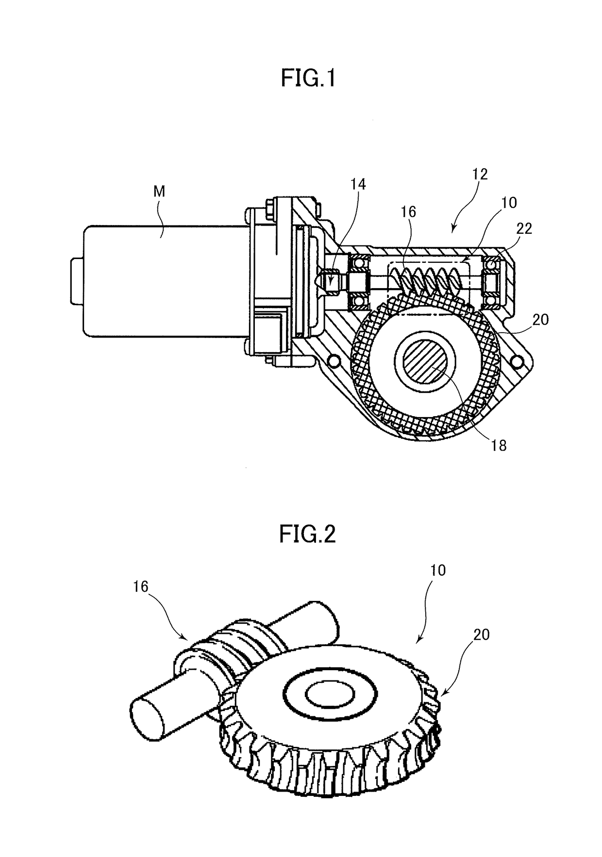
of Reduction Gear Mechanism
Examples 1-1 to 1-3
[0124]The worm wheels were prepared where the tooth surface roughness was optionally varied, and each test grease composition was applied to the tooth surfaces. With the worm and the worm wheel being meshed with each other under the same backlash conditions, the worm wheel of the worm gear was driven to rotate to determine the rotational torque was determined.
(Reduction Gear Mechanisms for the Test)
[0125]Worm wheels: injection-molded using glass fiber-reinforced polyamide PA66, and separately processed by gear cutting to have a surface roughness of 0.5 μm, 1.2 μm, and 1.5 μm in terms of the arithmetic mean roughness (Ra).[0126]Worm: made of steel, hardened by heat treatment and then finished by grinding.[0127]Shafts of the worm wheels and the worm: supported by the rolling bearings.[0128]Greases
[0129]Reference grease: prepared in the same manner as in Example 2 except that the hydrocarbon polymer was not used.
[0130]Grease of Example: The...
examples 2-1 to 2-3
[0136]The worms were prepared where the tooth surface roughness was optionally varied, and each test grease composition was applied to the tooth surfaces. With the worm and the worm wheel being meshed with each other under the same backlash conditions, the worm wheel of the worm gear was driven to rotate to determine the rotational torque.
(Reduction Gear Mechanisms for the Test)
[0137]Worms: made of steel, hardened by heat treatment and then finished by grinding. By changing the processing conditions, the worms having a surface roughness of 0.05 μm, 0.11 μm, and 0.22 μm in terms of the arithmetic mean roughness (Ra) were prepared.[0138]Worm wheel: injection-molded using glass fiber-reinforced polyamide PA66, and subjected to gear cutting.[0139]Shafts of the worm wheel and the worms: supported by the rolling bearings.[0140]Greases
[0141]Reference grease: prepared in the same manner as in Example 2 except that the hydrocarbon polymer was not used.
[0142]Grease of Example: The grease comp...
second embodiment
of Reduction Gear Mechanism
Example 3-1
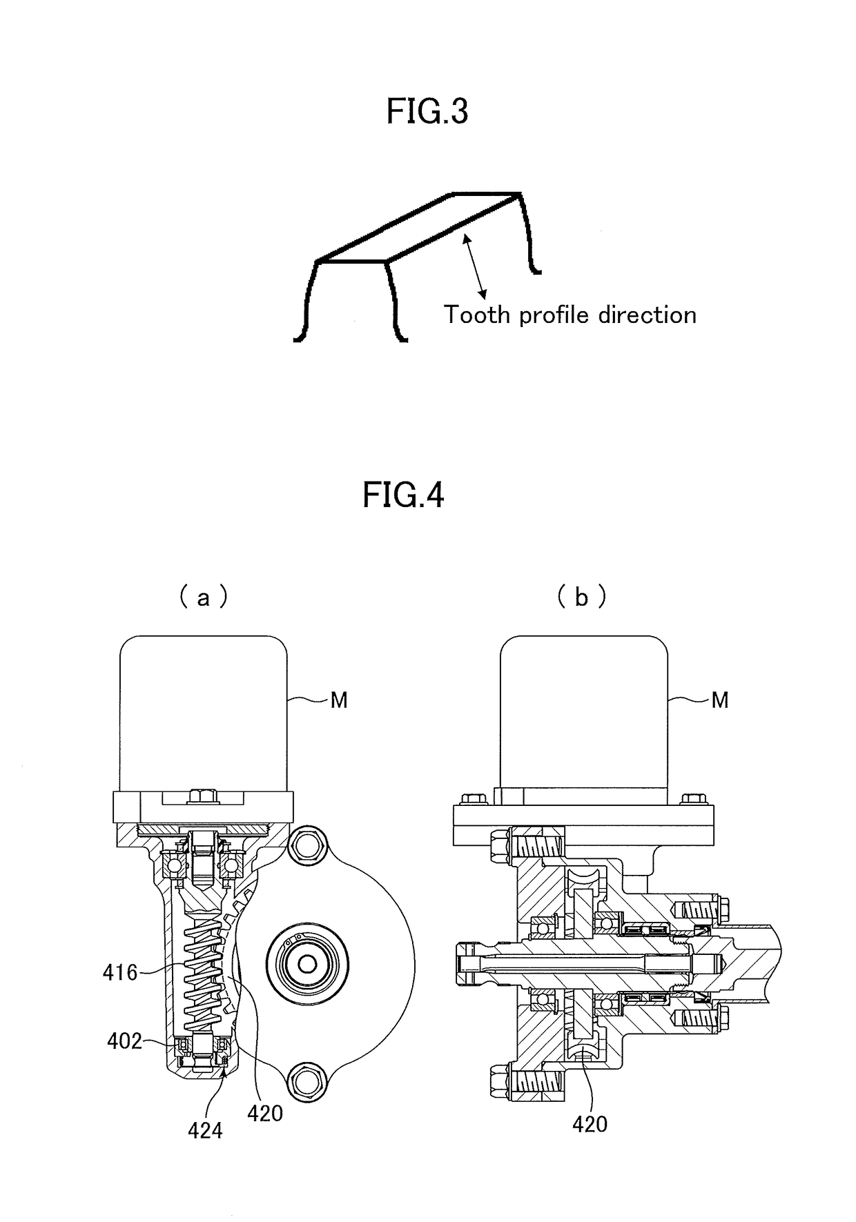
[0150]The load of the spring (i.e., an element of the urging mechanism for urging the worm toward the worm wheel, for example, the urging means 424 as shown in FIG. 4) was changed to four levels. For each load level, two reduction gear mechanisms were assembled so that the load was adjusted to the same level, and the reference grease and the grease of Example were separately applied. By driving the worm wheel shaft to rotate, the rotational torque was determined.
(Reduction Gear Mechanisms for the Test)
[0151]Springs: 1.0, 1.3, 1.7 and 2.0 (expressed by the ratio to 1.0, and the larger the value, the higher the load.)[0152]Worm wheel: injection-molded using glass fiber-reinforced polyamide PA66, and subjected to gear cutting to form tooth surfaces.[0153]Worm: made of steel, hardened by heat treatment and then finished by grinding.[0154]Shafts of the worm wheel and the worm: supported by the rolling bearings.[0155]Greases
[0156]Reference grease: pre...
PUM
| Property | Measurement | Unit |
|---|---|---|
| surface roughness | aaaaa | aaaaa |
| Ra | aaaaa | aaaaa |
| Ra | aaaaa | aaaaa |
Abstract
Description
Claims
Application Information