Internal combustion engine and control method of internal combustion engine

a control method and internal combustion engine technology, applied in the direction of electric control, machines/engines, output power, etc., can solve the problems of abnormal combustion such as pre-ignition or knocking, cylinder temperature may become excessively high, and the character switching mechanism is not considered, so as to prevent the occurrence of abnormal combustion

Active Publication Date: 2017-12-21
TOYOTA JIDOSHA KK
View PDF15 Cites 8 Cited by
  • Summary
  • Abstract
  • Description
  • Claims
  • Application Information

AI Technical Summary

Benefits of technology

[0019]According to this configuration, it is possible to prevent occurrence of abnormal combustion when a characteristic switching mechanism is out of order.

Problems solved by technology

However, in the technique disclosed in JP 2011-214477 A, a case in which the characteristic switching mechanism fails is not considered.
Accordingly, there is concern that the cylinder temperature may become excessively high in the operation range in which fuel is combusted by flame propagation combustion and abnormal combustion such as pre-ignition or knocking will occur.
The switching failure is failure in which the lift characteristic of the exhaust valve is not switchable from the second lift characteristic to the first lift characteristic using the characteristic switching mechanism.
The switching failure is failure in which the lift characteristic of the exhaust valve is not switchable from the second lift characteristic to the first lift characteristic by the electronic control unit.

Method used


Image

  • Internal combustion engine and control method of internal combustion engine
  • Internal combustion engine and control method of internal combustion engine
  • Internal combustion engine and control method of internal combustion engine

Examples


first embodiment

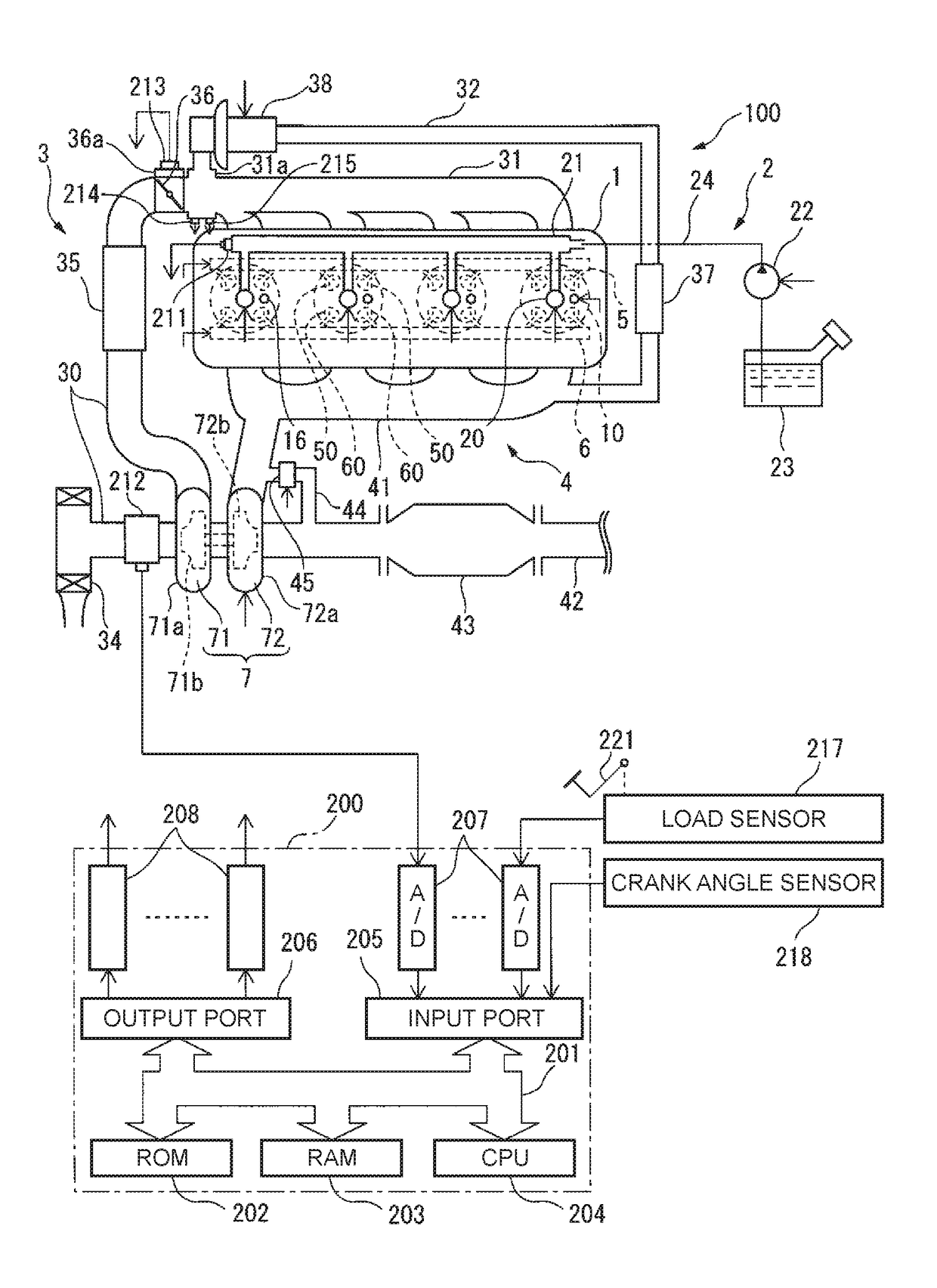
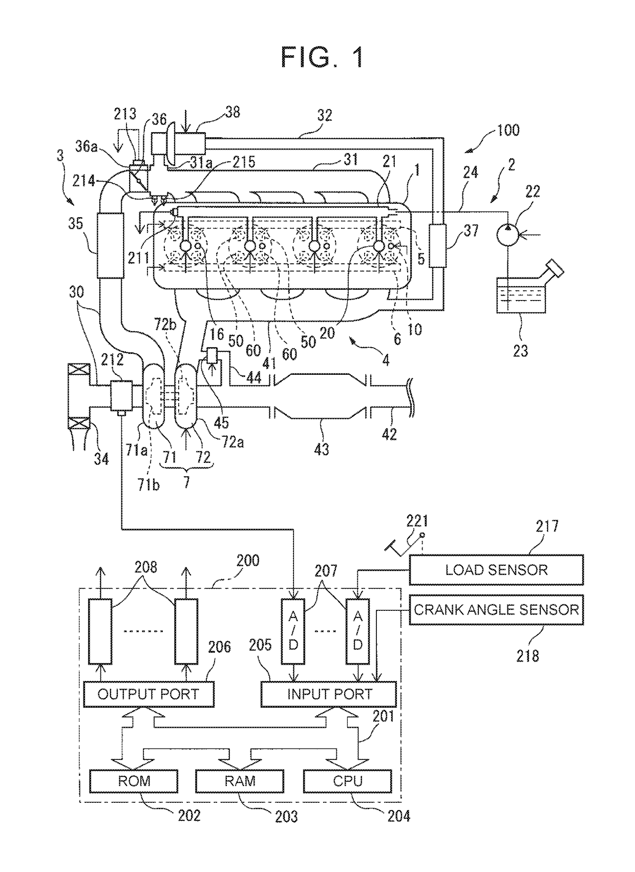
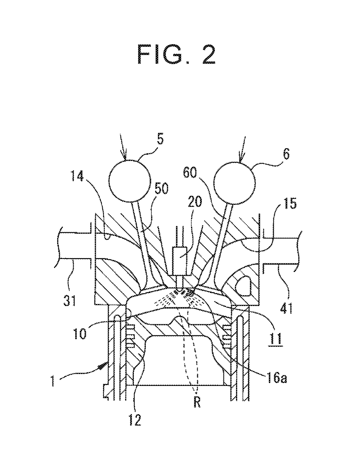
[0045]FIG. 1 is a diagram schematically illustrating configurations of an internal combustion engine 100 and an electronic control unit 200 that controls the internal combustion engine 100 according to the disclosure. FIG. 2 is a cross-sectional view of an engine body 1 of the internal combustion engine 100.

[0046]The internal combustion engine 100 includes an engine body 1 that includes a plurality of cylinders 10, a fuel supply device 2, an intake device 3, an exhaust device 4, an intake valve gear mechanism 5, and an exhaust valve gear mechanism 6.

[0047]The engine body 1 combusts fuel in a combustion chamber 11 (see FIG. 2) that is formed in each cylinder 10 and generates power for driving, for example, a vehicle. In the engine body 1, a spark plug 16 is disposed to face the combustion chamber 11 of the cylinder 10 for each cylinder. The engine body 1 is provided with a pair of intake valves 50 and a pair of exhaust valves 60 for each cylinder. As illustrated in FIG. 2, a piston 1...

second embodiment

[0152]the disclosure will be described below. In this embodiment, when switching failure has occurred, the operation mode is switched to the SGSI operation mode in the second operation range in which the exhaust valve twice-opening operation is not performed in the normal state, and control different from that in the normal state is performed on the throttle valve 36 and the waste gate valve 45. The differences will be mainly described below.

[0153]In the first embodiment, when switching failure has occurred, abnormal combustion or occurrence of misfiring is prevented by performing spray-guided stratified combustion in the second operation range in which the exhaust valve twice-opening operation is not performed in the normal state. However, when an amount of internal EGR gas increases, there is concern that abnormal combustion or occurrence of misfiring may not be satisfactorily prevented even when spray-guided stratified combustion is performed.

[0154]Therefore, in this embodiment, ...

third embodiment

[0205]In addition, the variable exhaust phase mechanism 63 may be controlled as in the In this case, for example, as illustrated in FIG. 19, by advancing the exhaust phase as much as possible using the variable exhaust phase mechanism 63 and delaying the intake phase as much as possible using the variable intake phase mechanism 53, it is possible to shorten a period in which the intake valve and the exhaust valve 60 are simultaneously opened in the intake stroke. Accordingly, it is possible to further decrease the amount of internal EGR gas and to further decrease the cylinder temperature, thereby further preventing occurrence of abnormal combustion or misfiring.

[0206]The electronic control unit 200 (the controller) according to this embodiment further includes an intake phase control unit that controls the variable intake phase mechanism 53 capable of changing the intake phase which is the phase of the intake cam shaft 51 with respect to the crank shaft. When switching failure has...


PUM


Abstract

An electronic control unit of an internal combustion engine is configured to control the fuel injection valve and to control a spark plug if necessary such that fuel is combusted by pre-mixture compression ignition combustion or flame propagation combustion. The electronic control unit is configured to perform homogeneous combustion in a flame ignition operation range when switching failure has not occurred, the homogeneous combustion being combustion in which fuel homogeneously diffused into the combustion chamber is ignited using the spark plug and is combusted by flame propagation combustion. The electronic control unit is configured to perform spray-guided stratified combustion in a second operation range when the switching failure has occurred, the spray-guided stratified combustion being combustion in which fuel in the fuel injection path is ignited using the spark plug and is combusted by the flame propagation combustion.

Description

INCORPORATION BY REFERENCE[0001]The disclosure of Japanese Patent Application No. 2016-120069 filed on Jun. 16, 2016 including the specification, drawings and abstract is incorporated herein by reference in its entirety.BACKGROUND1. Technical Field[0002]The disclosure relates to an internal combustion engine and a control method of an internal combustion engine.2. Description of Related Art[0003]Japanese Patent Application Publication No. 2011-214477 (JP 2011-214477 A) discloses an internal combustion engine including a characteristic switching mechanism that can switch a lift characteristic of an exhaust valve between a first lift characteristic in which the exhaust valve is opened in an exhaust stroke and a second lift characteristic in which the exhaust valve is opened in an exhaust stroke and an intake stroke. JP 2011-214477 A also discloses a controller for an internal combustion engine configured to switch the lift characteristic of the exhaust valve to the first lift characte...

Claims


Application Information

Patent Timeline
Patent Type & Authority Applications(United States)
IPC IPC(8): F02D13/02F01L1/344F02D41/30F02D41/22F01L1/047F02B37/22F02B37/18F02B1/12F02B1/02F02P15/00F02D41/00F02D41/38
CPCF02D13/0219F02D41/0002F02D13/0273F02P15/006F02B1/12F02B1/02F02D2041/001F02D41/3029F02B37/22F02B37/18F01L1/344F01L1/047F02D2041/389F02D41/221F02D45/00F02D2200/0406F02D2200/0414F02D2200/0602F02B11/00F02B11/02F02B17/005F02B23/105F02D41/006F02D41/3035F02M26/01F02M26/49Y02T10/12Y02T10/40F02D9/02F02D13/0246F02D37/02F02D13/0207
Inventor OKADA, YOSHIHIROTSURU, FUMITSUGU
Owner TOYOTA JIDOSHA KK
Why Eureka
Try Eureka